Non-volatile storage
a non-volatile storage and storage technology, applied in the field of non-volatile storage, can solve the problems of increasing the number of dram chips, increasing the cost, and needing large-capacity dram, so as to reduce the manufacturing cost, save space, and high access performance
- Summary
- Abstract
- Description
- Claims
- Application Information
AI Technical Summary
Benefits of technology
Problems solved by technology
Method used
Image
Examples
embodiment
Outline of Embodiment
[0039]An outline of the embodiment will be explained first. In the outline of this embodiment, as one example, the explanation will be given with corresponding components and symbols of each embodiment being put in parentheses.
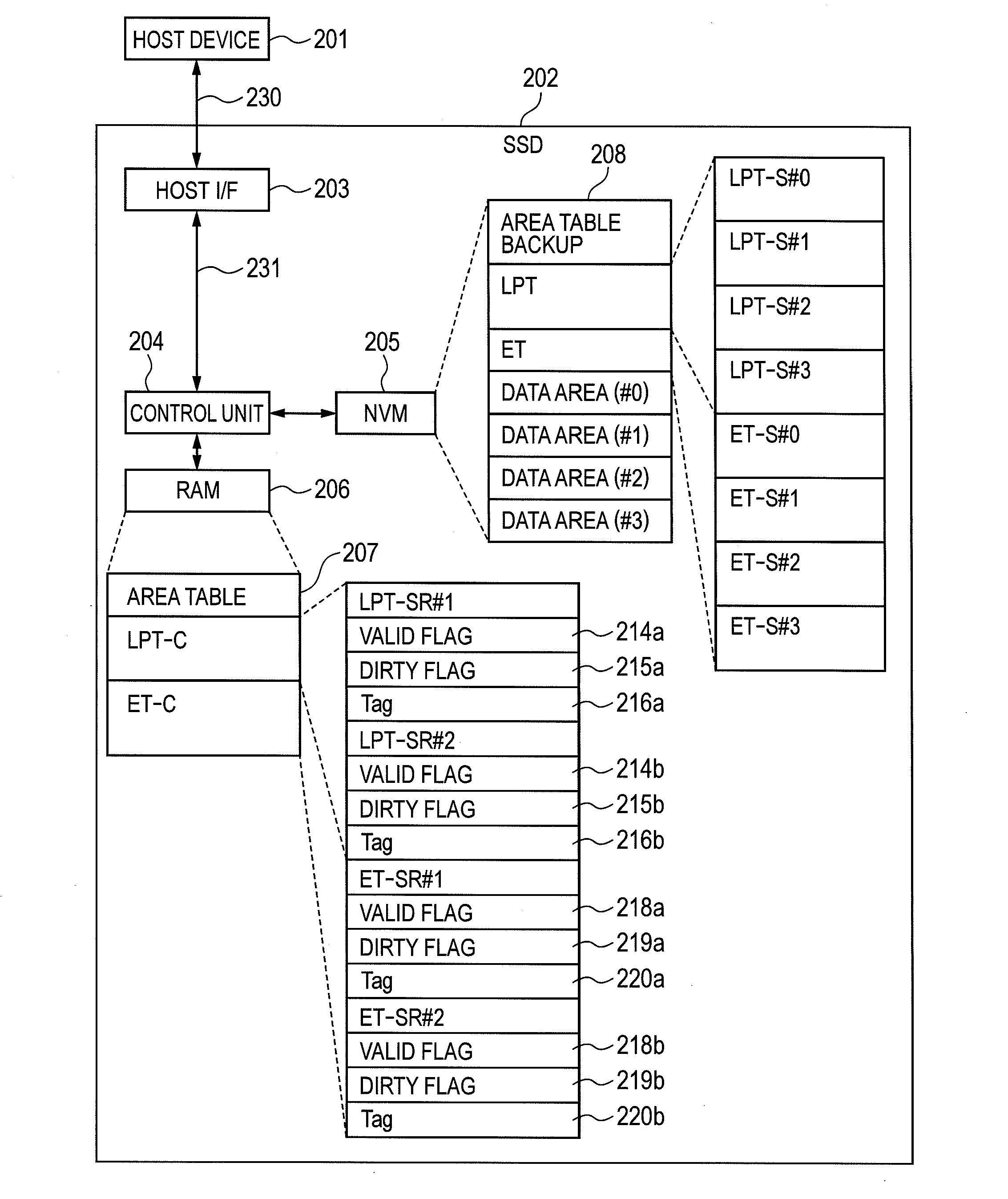
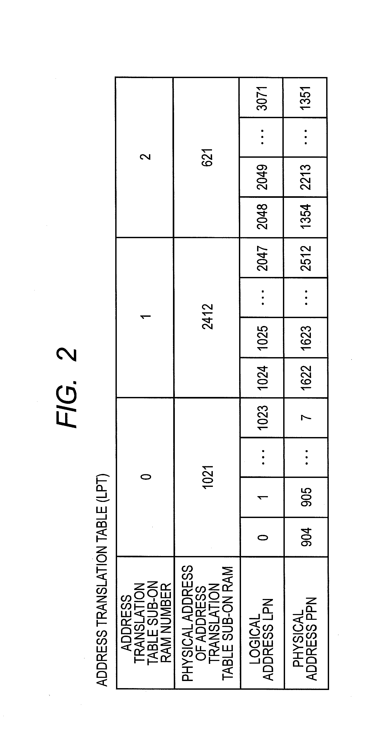
[0040](1) A representative non-volatile storage (an SSD 202) of the embodiment has first memory of non-volatile type (an NVM 205), second memory (RAM 206) capable of being accessed faster than the first memory, and a control unit (a control unit 204) for controlling accesses to the first memory and to the second memory. Then, the control unit is characterized by storing in the first memory an address translation table (an address translation table LPT) for translating a logical address given in order to access the first memory to a physical address with the table being divided into multiple partial address translation tables, and further storing in the second memory more than one partial address translation tables of the partial address tr...
first embodiment
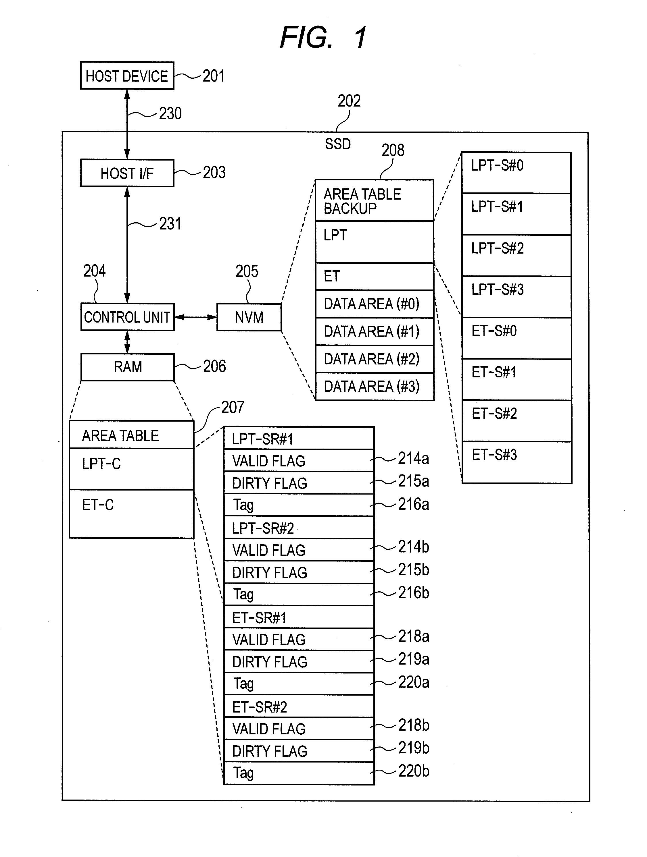
[0044]A non-volatile storage of a first embodiment will be explained using FIG. 1 to FIG. 15.
[0045]In this embodiment, an example of the non-volatile storage (SSD: Solid State Drive) will be explained. Below, this non-volatile storage may be described as an SSD. Moreover, non-volatile memory (NVM: Non-Volatile Memory) that forms this non-volatile storage may be described as an NVM. Furthermore, other components may be described by abbreviated names.
[0046]A configuration of the non-volatile storage (SSD) of this embodiment will be explained using FIG. 1. Together with this, a connection between the SSD and the host device will also be described. FIG. 1 is a diagram showing one example of this configuration of the SSD.
[0047]The SSD 202 is comprised of a host interface (I / F) 203, the control unit 204 connected to this host I / F 203 with an interface 230, the NVM 205 connected to this control unit 204, and RAM 206 connected to this control unit 204.
[0048]This SSD 202 is connected with a ...
second embodiment
[0206]A non-volatile storage of a second embodiment will be explained using FIG. 16 and FIG. 17. FIG. 16 is a diagram showing one example configuration of this non-volatile storage (SSD) 202. FIG. 17 is a diagram of a modification configuration of the SSD 202.
[0207]In this embodiment, an example of the SSD 202 that not only has a reduced mounting cost of the volatile memory and high access performance but also has higher access performance than the above-mentioned first embodiment will be explained.
[0208]The phase change memory is used as the non-volatile memory (NVM). Especially, it is desirable to use three-dimensional stacked phase change memory 3D-PCM (3 Dimension Phase Change Memory) that has a large capacity is used.
[0209]A configuration of the SSD 202 in the second embodiment will be explained using FIG. 16. Explanations are omitted for configurations to which the same symbols shown in FIG. 1 and explained in the first embodiment already described above are given and portions...
PUM
 Abstract
Description
Claims
Application Information
 - R&D
- Intellectual Property
- Life Sciences
- Materials
- Tech Scout
- Unparalleled Data Quality
- Higher Quality Content
- 60% Fewer Hallucinations
Browse by: Latest US Patents, China's latest patents, Technical Efficacy Thesaurus, Application Domain, Technology Topic, Popular Technical Reports.
© 2025 PatSnap. All rights reserved.Legal|Privacy policy|Modern Slavery Act Transparency Statement|Sitemap|About US| Contact US: help@patsnap.com


