Endovascular tissue removal device

a tissue removal and endovascular technology, applied in the field of endovascular tissue removal devices, can solve the problems of collateral damage, difficult control of monopolar devices, etc., and achieve the effect of enhancing the mechanical breakup of tissu

Active Publication Date: 2015-06-16
TYCO HEALTHCARE GRP LP
View PDF58 Cites 15 Cited by
  • Summary
  • Abstract
  • Description
  • Claims
  • Application Information

AI Technical Summary

Benefits of technology

[0011]In one embodiment, the catheter insert has a fluted configuration and is positioned within the catheter to define the fluid channel. The electrode may also have a fluted configuration and is supported on a distal end of the catheter insert. A distal face of the electrode may define on abrasive surface to enhance the mechanical breakup of tissue.

Problems solved by technology

However, monopolar devices typically are more difficult to control to limit collateral damage.

Method used


Image

  • Endovascular tissue removal device
  • Endovascular tissue removal device
  • Endovascular tissue removal device

Examples


Embodiment Construction

[0031]Embodiments of the presently disclosed endovascular tissue removal device will now be described in detail with reference to the drawings wherein like reference numerals identify similar or identical elements. As used herein, the term “distal” refers to that portion of the device which is furthest from the user while the term “proximal” refers to that portion of the device which is closer to the user. In the following description, well known functions or constructions are not described in detail to avoid obscuring the present disclosure in unnecessary detail.

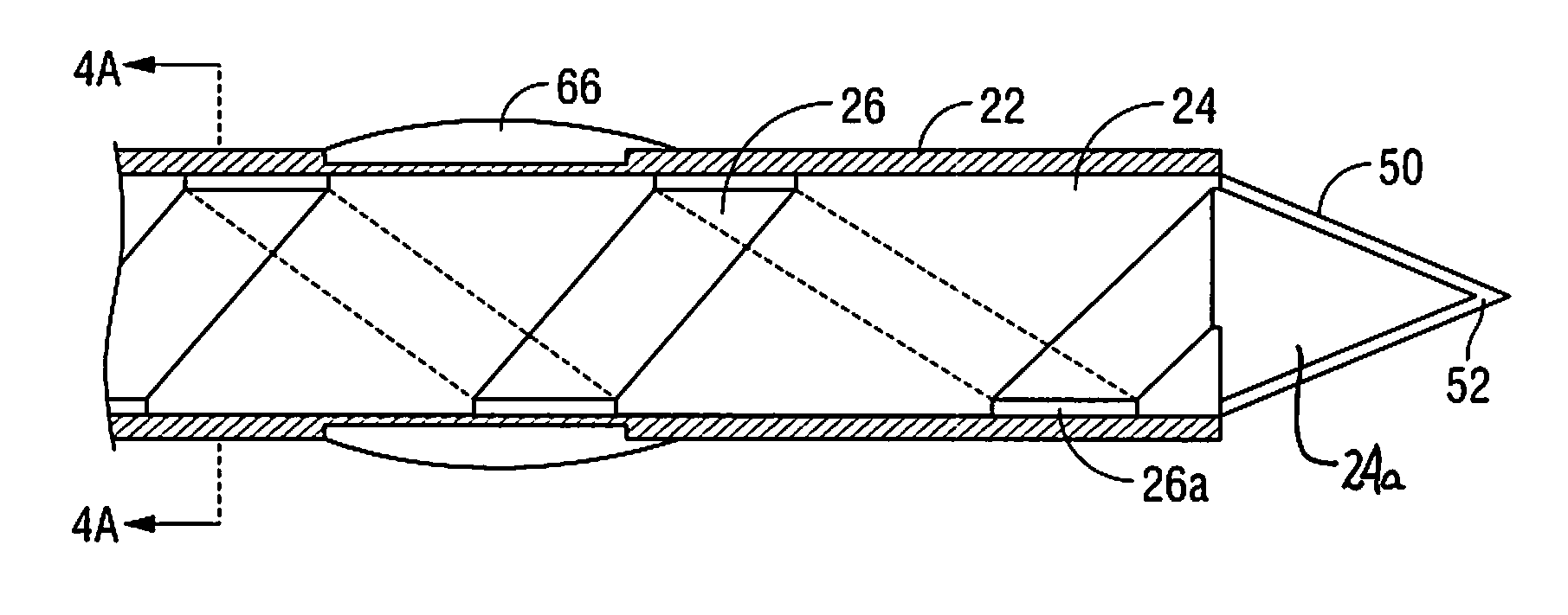
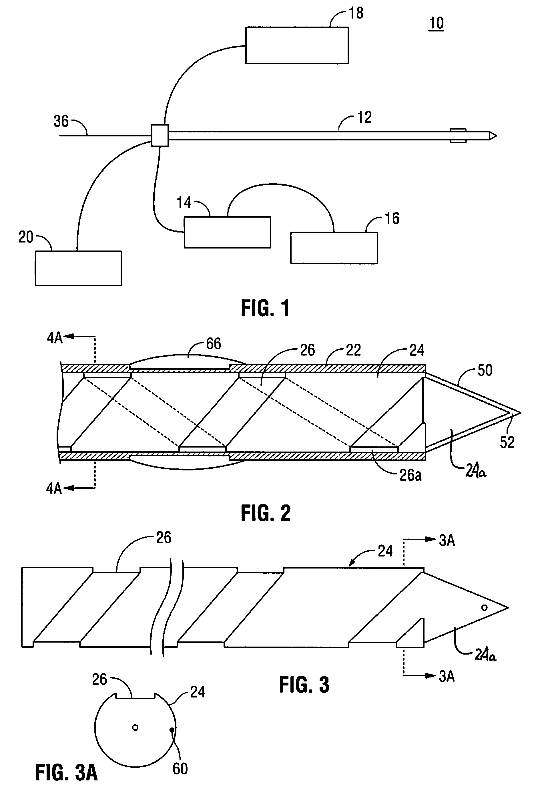
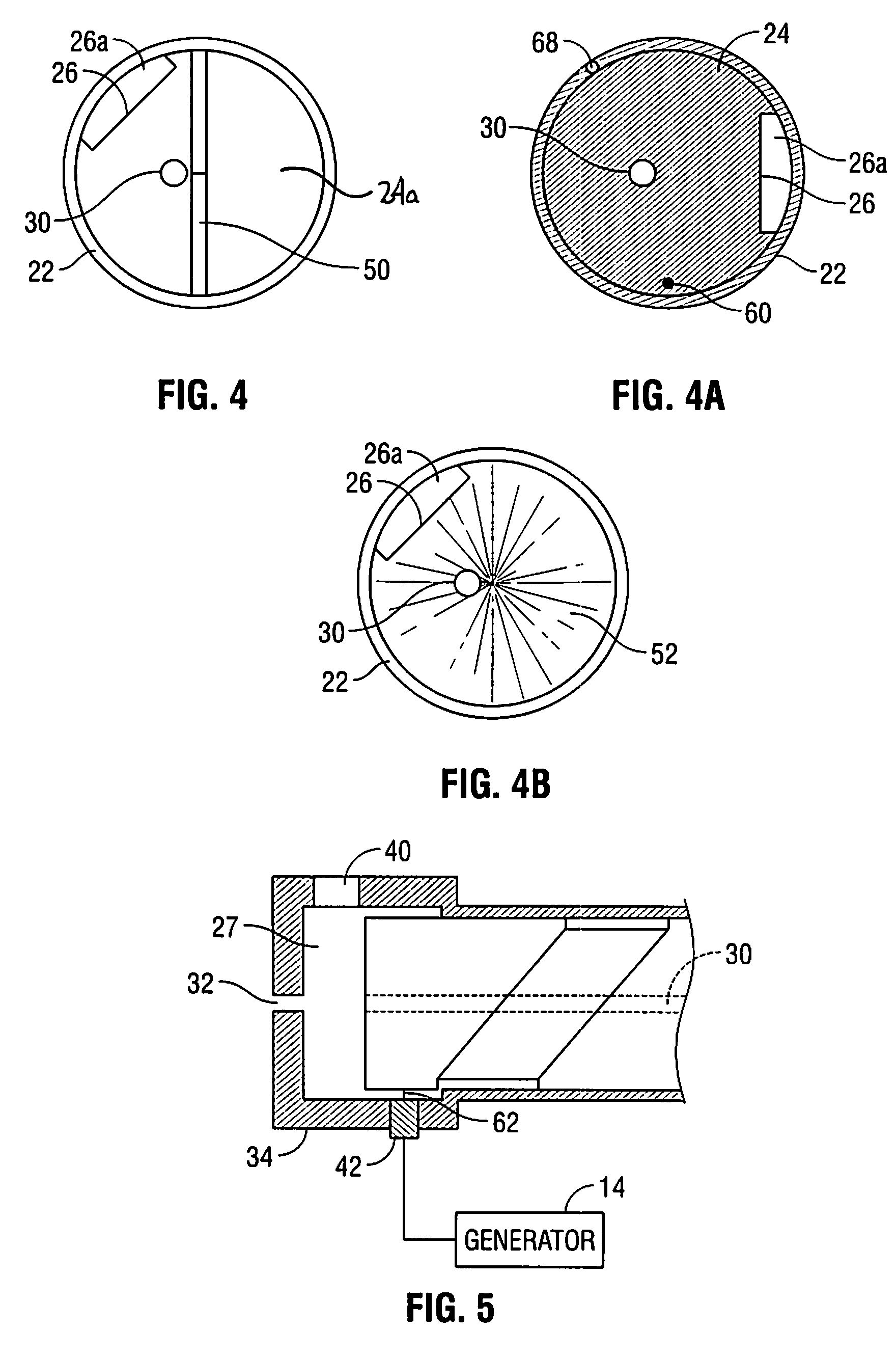
[0032]FIG. 1 is a schematic illustration of a monopolar electrosurgical system 10 according to one embodiment of the present disclosure. The system 10 includes a tissue removal device 12, an RF generator 14, a ground pad 16, a pressurized source of fluid 18, and a fluid suction / supply device 20. Referring also to FIGS. 2-5, the tissue removal device 12 includes an outer catheter 22 and a catheter insert 24. Catheter insert ...


PUM


Abstract

A monopolar electrosurgical apparatus is disclosed which includes a tissue removal device having electrical, mechanical and chemical tissue removal capabilities. The device can be operated to use any of its tissue removal capabilities alone or in combination with one or more of the other capabilities.

Description

BACKGROUND[0001]1. Technical Field[0002]The present disclosure relates to electrosurgical apparatus, system and methods. More particularly, the present disclosure relates to an endovascular tissue removal device.[0003]2. Background of Related Art[0004]Apparatus, as well as systems and methods, which use electrosurgical energy to maintain or create patency in a body vessel are well known in the art. Electrosurgical apparatus apply electrical energy, such as, radio frequency electrical current, microwave energy or resistive heating, to a surgical site to cut, ablate, coagulate or seal tissue.[0005]Two types of electrosurgical apparatus include bipolar and monopolar apparatus. A bipolar electrosurgical apparatus typically includes a handheld device including both an active electrode and a return electrode. The return electrode is placed in close proximity to the active electrode such that an electrical circuit is formed between the two electrodes. In use, it is the intent that the appl...

Claims


Application Information

Patent Timeline
Patent Type & Authority Patents(United States)
IPC IPC(8): A61B18/14A61B18/00A61F2/958
CPCA61B18/1492A61B2018/00285A61B2018/00422A61B2018/1472A61B2218/002A61B2218/007
Inventor DESHPANDE, MANISH
Owner TYCO HEALTHCARE GRP LP
Why Eureka
Try Eureka