System for cooling vehicle-mounted power control device and method for diagnosing abnormality

a power control device and hybrid vehicle technology, applied in electric devices, machine/engines, battery/fuel cell control arrangements, etc., can solve the problems of reducing detection accuracy, reducing the output value of intake temperature sensors, and increasing the number of components and costs, so as to achieve effective utilization

Active Publication Date: 2016-07-05
HINO MOTORS LTD
View PDF26 Cites 1 Cited by
  • Summary
  • Abstract
  • Description
  • Claims
  • Application Information

AI Technical Summary

Benefits of technology

[0009]An objective of the present disclosure is to provide a system for cooling a vehicle-mounted power control device and a method for diagnosing abnormality that improve accuracy of abnormality diagnosis according to an ambient temperature without increasing the number of components.
[0011]According to this aspect, the intake temperature detected by the intake temperature sensor is used to detect whether the ambient temperature is in a low temperature range or a high temperature range. Thus, the ambient temperature can be detected by effectively utilizing the intake temperature sensor without separately providing an ambient temperature sensor for abnormality diagnosis. Furthermore, the timing of using the output value of the intake temperature sensor is limited to when the reference intake amount is ensured, which is when influence of heat from the engine is eliminated so that the intake temperature becomes substantially equal to the ambient temperature. Accordingly, accurate detection of the ambient temperature reduces the possibility of falsely determining abnormality of the cooling device.
[0015]According to this aspect, the electronic control device refrains from determining presence or absence of a broken wire in the cooling medium temperature detection section, which has resistance increasing as the temperature decreases, when the ambient temperature is in the low temperature range. When the ambient temperature is not in the low temperature range and the cooling medium temperature detection section outputs a value in the output range for a broken wire, the electronic control device determines that a wire is broken. This reduces the possibility of falsely determining that a wire is broken although no wire is broken only based on a value output when a temperature is low. Furthermore, it is avoidable to falsely determine that the ambient temperature is not in the low temperature range when actually it is by using the intake temperature detected in the reference traveling state. This reduces the possibility of falsely determining that a wire is broken although no wire is broken.
[0017]According to this aspect, the electronic control device determines that the battery is abnormally cooled if the detected battery temperature value input by the battery temperature detection section is less than the intake temperature input by the intake temperature sensor and the difference between the intake temperature and the detected battery temperature value is greater than or equal to the threshold. Thus, it is possible to detect a state of the battery, e.g., a state in which the battery is frozen. Furthermore, the electronic control device is configured to use the intake temperature detected when the vehicle is in the reference traveling state. Accordingly, it is avoidable to falsely determine that the ambient temperature is not in the low temperature range when actually it is. This reduces the possibility of falsely determining that the battery is abnormally cooled simply due to a low surrounding temperature of the battery.
[0019]According to this aspect, the intake temperature detected by the intake temperature sensor is used to determine whether the ambient temperature is in the low temperature range or in the high temperature range. Thus, the intake temperature sensor is effectively utilized to detect a temperature substantially the same as the ambient temperature without separately providing an ambient temperature sensor for abnormality diagnosis. Furthermore, the timing of using the output value of the intake temperature sensor is limited to when the intake amount is ensured to be greater than or equal to the reference intake amount. With the timing, the ensured reference intake amount eliminates influence of heat from the engine so that the intake temperature is substantially equal to the ambient temperature. Accordingly, accurate detection of the ambient temperature reduces the possibility of falsely determining abnormality of the cooling device.

Problems solved by technology

When an ambient temperature sensor is provided for a cooling system, the number of components and the costs increase.
Although it is preferable to effectively utilize an existing temperature sensor provided for the vehicle, heat discharged from the combustion chamber of the engine and other factors may affect some temperature sensors to decrease detection accuracy.
Such problems are not limited to a cooling system configured as mentioned above, but also apply to most of systems for cooling a vehicle-mounted power control device.
Furthermore, the timing of using the output value of the intake temperature sensor is limited to when the reference intake amount is ensured, which is when influence of heat from the engine is eliminated so that the intake temperature becomes substantially equal to the ambient temperature.
Accordingly, accurate detection of the ambient temperature reduces the possibility of falsely determining abnormality of the cooling device.

Method used


Image

  • System for cooling vehicle-mounted power control device and method for diagnosing abnormality
  • System for cooling vehicle-mounted power control device and method for diagnosing abnormality
  • System for cooling vehicle-mounted power control device and method for diagnosing abnormality

Examples


first embodiment

[0026]A system for cooling a vehicle-mounted power control device and a method for diagnosing abnormality of the power control device according to a first embodiment will now be described with reference to FIGS. 1 to 5.

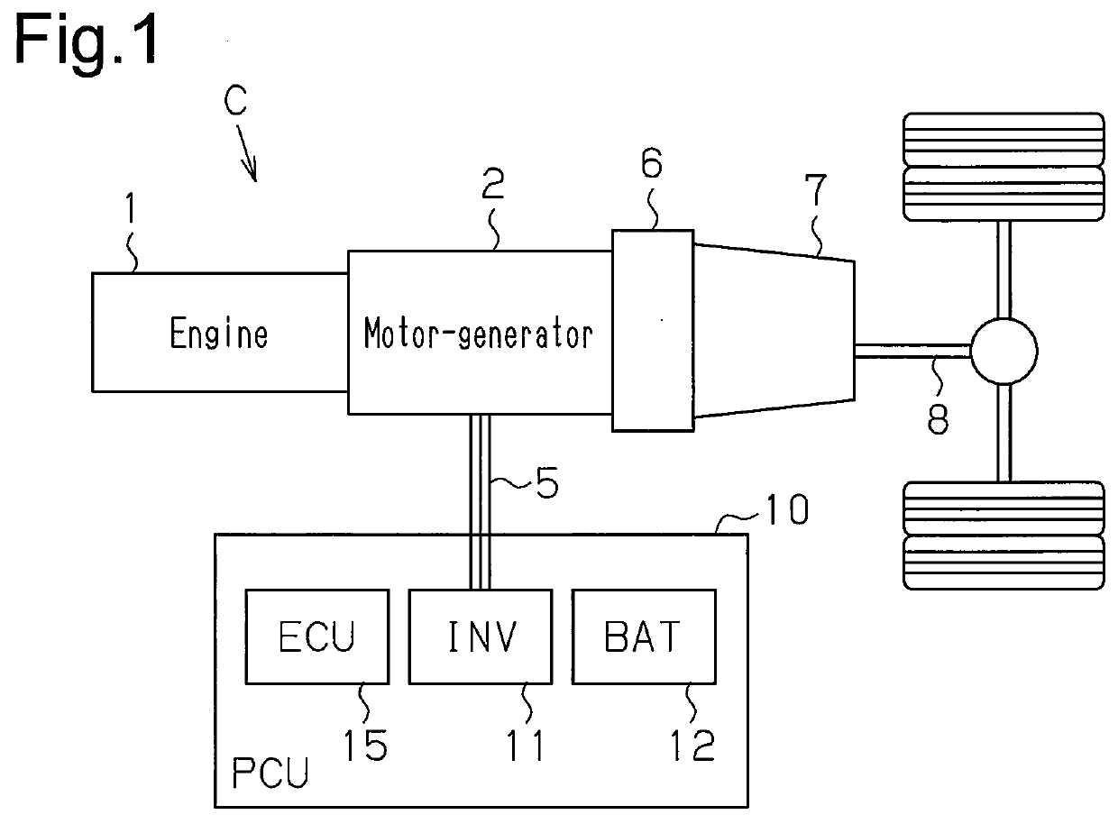
[0027]As shown in FIG. 1, a hybrid vehicle C includes an engine 1, a motor-generator 2, which functions as a rotating electrical machine, and a gear mechanism (not shown), which couples the engine 1 to the motor-generator 2. The motor-generator 2 is connected to a power control unit (PCU) 10 with a three-phase cable 5. The motor-generator 2 is also coupled to a transmission 7 via a clutch 6. The transmission 7 has an output shaft coupled to a drive shaft 8 of the vehicle.

[0028]The PCU 10 includes an inverter 11 for a hybrid vehicle, a battery module 12 including a plurality of cells, and an ECU 15, which functions as an electronic control system. The inverter 11 is connected to the motor-generator 2 with the three-phase cable 5. The battery module 12 is electrically c...

second embodiment

[0062]A system for cooling a vehicle-mounted power control device and a method for diagnosing abnormality of the power control device according to a second embodiment will now be described with reference to FIG. 6. Only the diagnosing method in the configuration according to the first embodiment is modified in the configuration according to the second embodiment. Thus, like reference characters designate like or corresponding parts and the parts will not be described in detail.

[0063]According to the present embodiment, the battery module 12 is subject to diagnosis in which whether it is abnormally cooled is determined. As shown in FIG. 6, when a process of abnormal cooling diagnosis is started, the ECU 15 receives input of the vehicle speed S from the vehicle speed sensor 35 (step S1-1) and sets the reference speed Smin and the reference time Dmin according to the traveling mode of the vehicle C at that moment (step S1-2). The ECU 15 then determines whether the received vehicle spee...


PUM


Abstract

A system for cooling a power control device of a hybrid vehicle includes a cooling device for cooling a power control device, an electronic control device for controlling the cooling device, and an intake temperature sensor. The electronic control device determine whether the vehicle is in a reference traveling state with an intake amount ensured to be greater than or equal to a reference intake amount. When determining that the vehicle is in the reference traveling state, the control device determines presence or absence of abnormality in the cooling device using an intake temperature detected by the intake temperature sensor. When determining that the vehicle is not in the reference traveling state, the control device refrains from determining presence or absence of abnormality in the cooling device.

Description

CROSS REFERENCE TO RELATED APPLICATIONS[0001]This application is a national stage application under 35 U.S.C. 371 and claims priority to and the benefit of PCT Application No. PCT / JP2013 / 077292 having an international filing date of Oct. 8, 2013, which designated the United States, which PCT application claimed priority to and the benefit of Japanese Patent Application No. 2012-226663 filed Oct. 12, 2012, the disclosures of each of which are incorporated herein by reference.FIELD OF THE INVENTION[0002]The techniques of the present disclosure relate to a system for cooling a power control device mounted on a hybrid vehicle and a method for diagnosing abnormality of the power control device.BACKGROUND OF THE INVENTION[0003]A hybrid vehicle has an engine and a rotating electrical machine as drive sources. A power control device mounted on the hybrid vehicle includes a battery module, which includes a plurality of battery cells, and an inverter, which converts direct-current power outpu...

Claims


Application Information

Patent Timeline
Patent Type & Authority Patents(United States)
IPC IPC(8): B60L11/18B60W20/00B60K11/02B60K11/06B60L3/00B60L50/16
CPCB60W20/50B60K11/02B60K11/06B60L3/0038B60L11/1851Y10S903/903B60L50/16B60K6/485B60L1/003B60L3/003B60L3/0084F01P2025/13F01P2050/24B60K2001/003B60L2240/36B60L2240/662B60L2240/525B60L2210/40B60L2200/36Y02T90/16Y02T10/70B60L3/00B60W10/00B60W10/26B60W10/30B60W20/00B60L58/10B60L58/26Y02T10/62Y02T10/72Y02T10/7072
Inventor MASUDA, MANABUSURUGA, TAKAYUKIMIZOROKI, SHIN
Owner HINO MOTORS LTD
Why Eureka
Try Eureka