
Lighting device with microwave detection function
a technology of microwave detection and light source, which is applied in the field of light source, can solve the problems of difficult maintenance of the lamp system by an ordinary person, difficulty in adding an omnidirectional detection function to the infrared sensor, and large power consumption of the lamp system, so as to simplify and simplify the design of the digital signal processor of the conventional microwave sensor. , the effect of reducing the size of the microwave sensor
Patent Information
- Authority / Receiving Office
- US · United States
- Patent Type
- Patents(United States)
- Current Assignee / Owner
- Publication Date
- 2016-08-23
- Estimated Expiration
- Not applicable · inactive patent
Smart Images
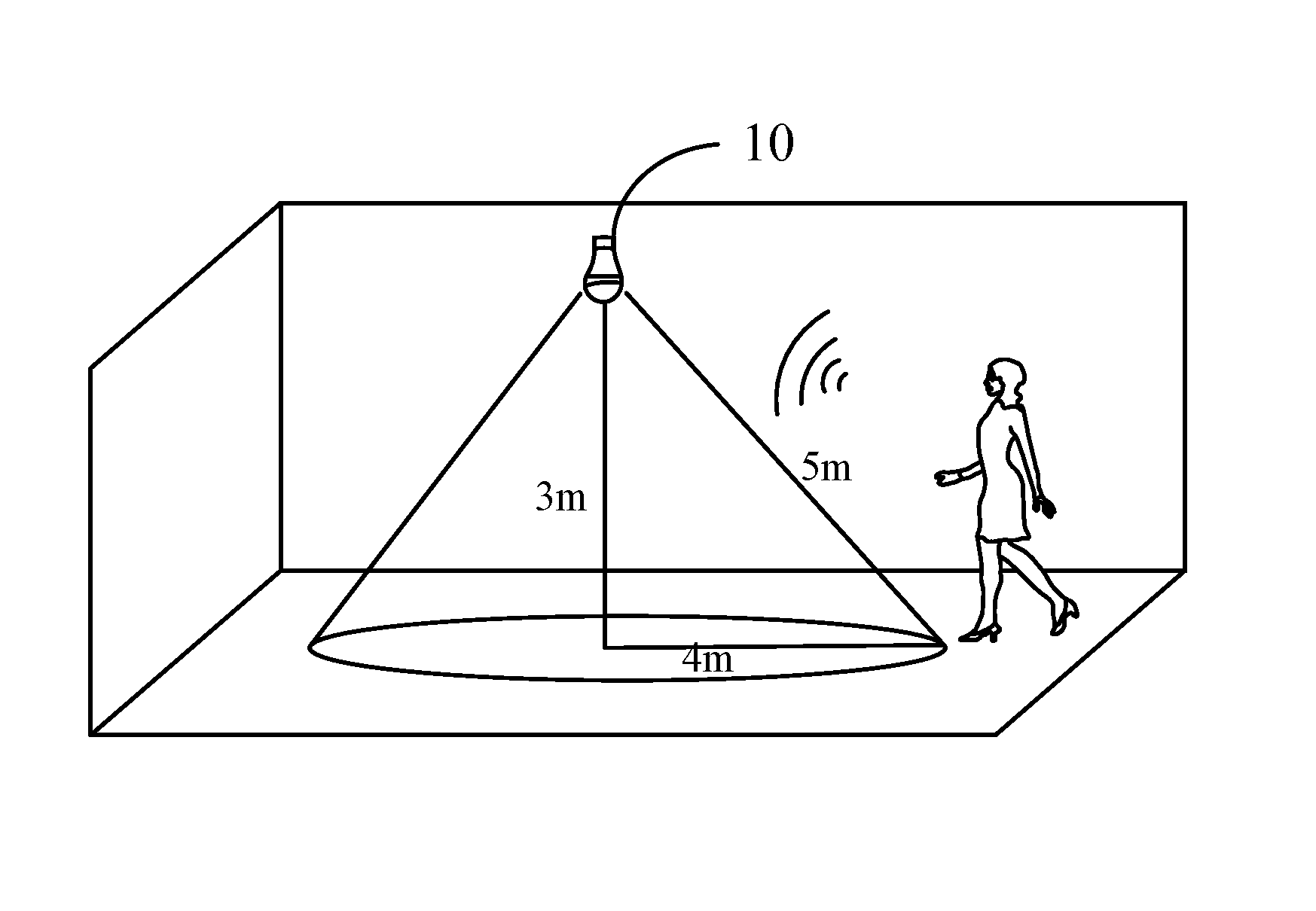
Figure 1 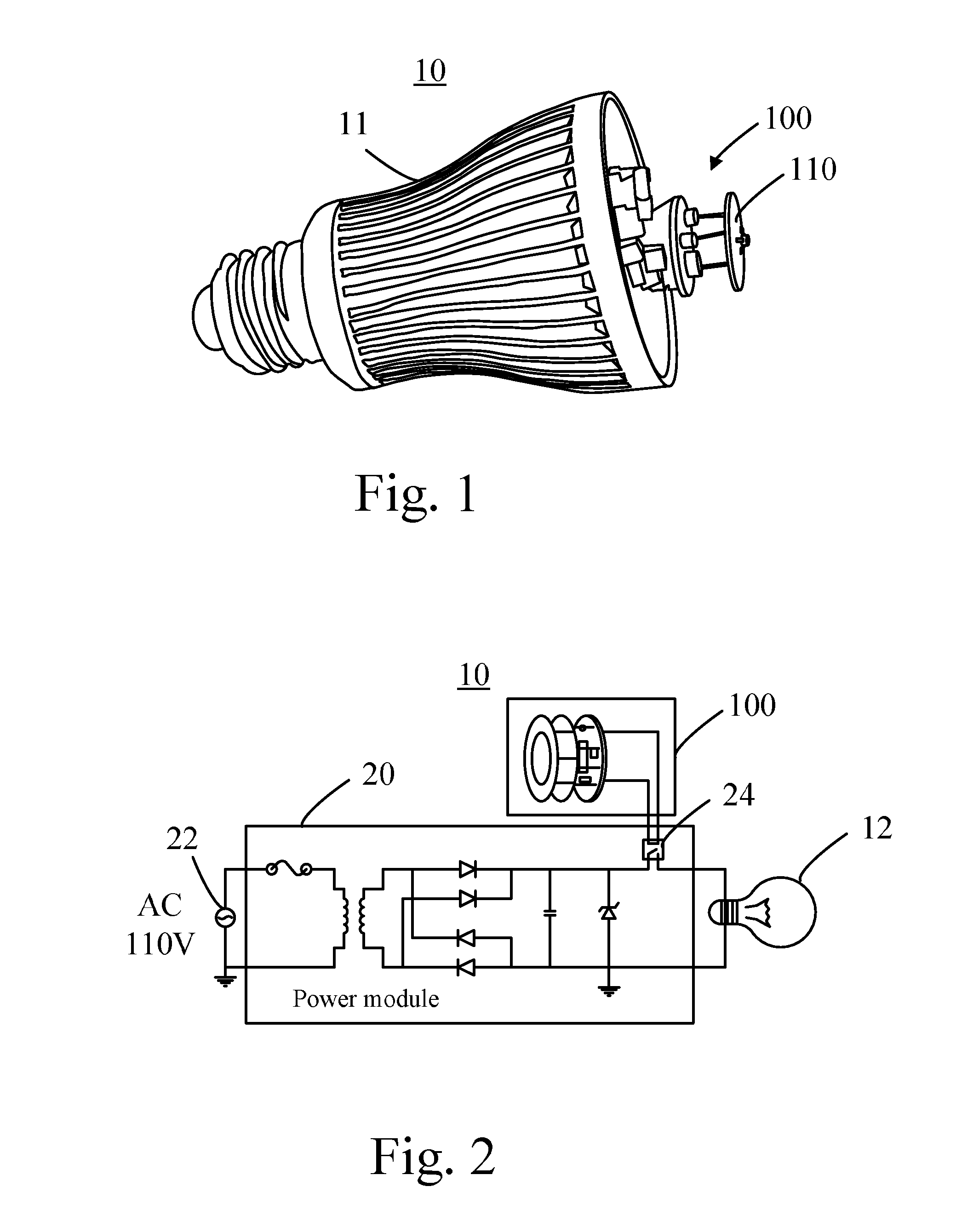
Figure 2 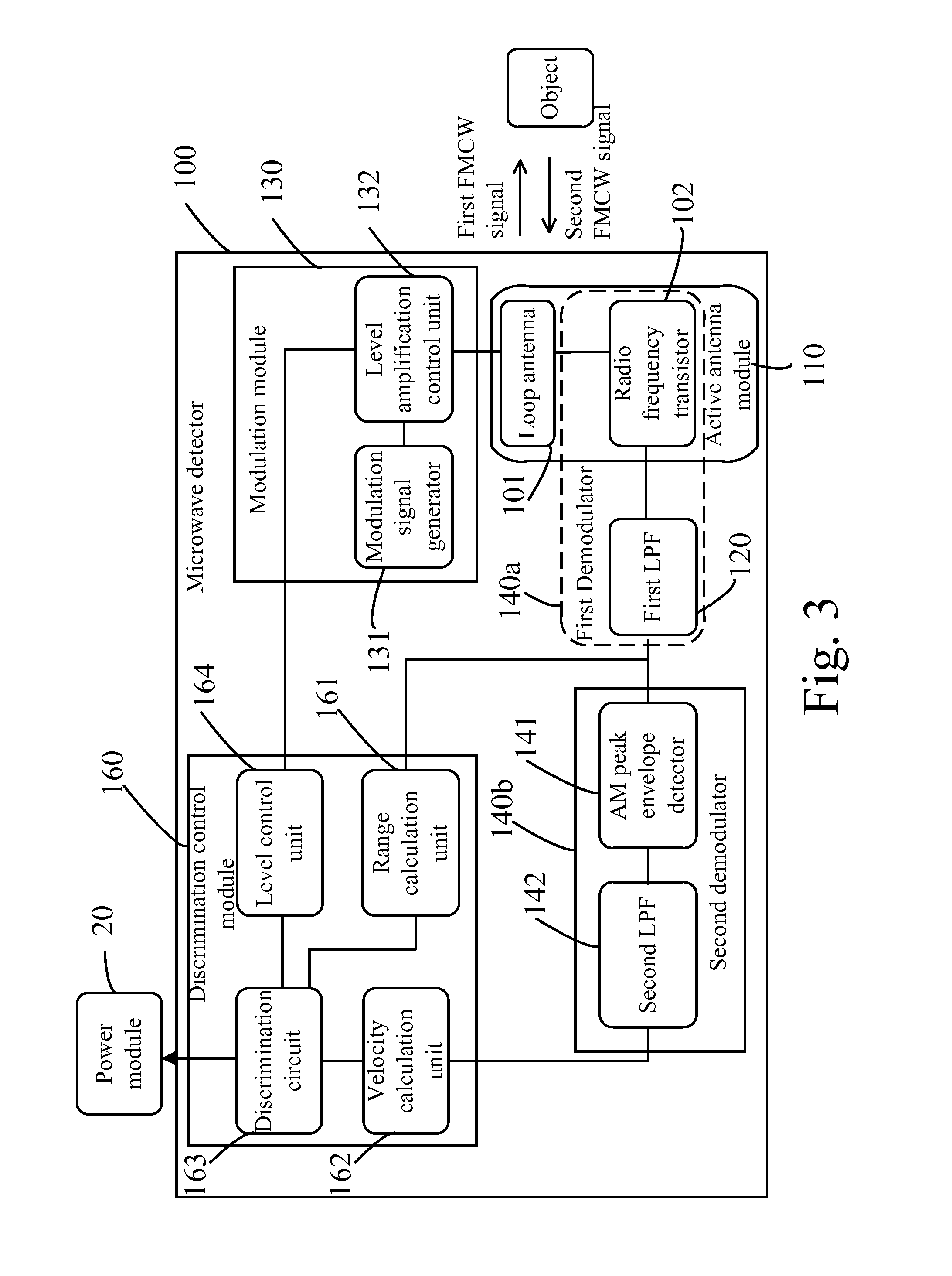
Figure 3
Abstract
Description
CROSS REFERENCE TO RELATED APPLICATION
[0001] This application claims priority to Taiwan Application Serial Number 102132290, filed on Sep. 6, 2013, which are herein incorporated by reference.BACKGROUND OF THE INVENTION
[0002] 1. Field of the Invention
[0003] The present invention relates to a lighting device, and more particularly, to a lighting device has a microwave detection function for sensing range and velocity of a moving target.
[0004] 2. Description of the Prior Art
[0005] According to modern intelligent smart homecare and energy-saving requirements, a switch of a lamp or strength of illumination of a lamp in most of lighting devices is designed with a power-saving and energy-saving structure. A common low-power miniature sensor is divided into two types—an infrared sensor and a microwave sensor. The infrared sensor is an electronic device which senses a moving object. The infrared sensor senses movement of the object with variation of infrared ray emitted by a human being. The micr...
Examples
Embodiment Construction
[0039]Spatially relative terms, such as “beneath”, “below”, “lower”, “above”, “upper” and the like, may be used herein for ease of description to describe one element or feature's relationship to another element(s) or feature(s) as illustrated in the figures. It will be understood that the spatially relative terms are intended to encompass different orientations of the device in use or operation in addition to the orientation depicted in the figures.
[0040]Please refer to FIG. 1 and FIG. 2. FIG. 1 illustrates a lighting device 10 according to an embodiment of the present invention. FIG. 2 is a functional block diagram showing the lighting device 10. The lighting device 10 comprises a lamp body 11, a light source 12, a microwave sensor 100, and a power module 20. The light source 12 may be a light emitting diode (LED). The microwave sensor 100 integrates a conventional active antenna and a conventional radio frequency (RF) module for calculating a range between the microwave sensor 10...