Detecting apparatus and image forming apparatus including the same

a detection apparatus and image technology, applied in the field of detection apparatuses, can solve the problems of paper deterioration in image quality, requiring a lot of time to output multiplexed images or full color images, and color misregistration has been a big problem, so as to achieve the effect of simplifying and reducing the siz

Inactive Publication Date: 2014-01-07
CANON KK
View PDF3 Cites 0 Cited by
  • Summary
  • Abstract
  • Description
  • Claims
  • Application Information

AI Technical Summary

Benefits of technology

[0010]An object of the present invention is to provide a detecting apparatus capable of detecting a pattern image for position detection formed on a recording member (image bearing member) by securing sufficient space between both substrates of a light source unit and a light receiving unit in terms of layout and performing appropriate adjustment while achieving overall downsizing and simplification.
[0023]According to the present invention, the detecting apparatus capable of detecting the pattern image for position detection formed on the recording member (image bearing member) by securing sufficient space between both the substrates of the light source unit and the light receiving unit in terms of layout and performing appropriate adjustment while achieving overall downsizing and simplification can be obtained.

Problems solved by technology

In a case of obtaining a full color image by performing multiple color developing, even a slight overlap positional deviation of the paper deteriorates image quality.
However, this method has a problem of requiring much time to output a multiplexed image or a full color image.
However, in this method, a color misregistration has been a big problem, which is caused when overlaying the images of the respective colors one on another on the paper.
However, this method is subject to a large number of constraints in terms of layout because a substrate of a light source unit and a substrate of the light receiving unit are in so close vicinity to each other as to cause interference therebetween.
Further, if the substrates are brought into close vicinity to each other with less space therebetween, it becomes difficult to appropriately adjust positions of respective members, which causes the occurrence of a large number of color misregistrations.

Method used


Image

  • Detecting apparatus and image forming apparatus including the same
  • Detecting apparatus and image forming apparatus including the same
  • Detecting apparatus and image forming apparatus including the same

Examples


example 1

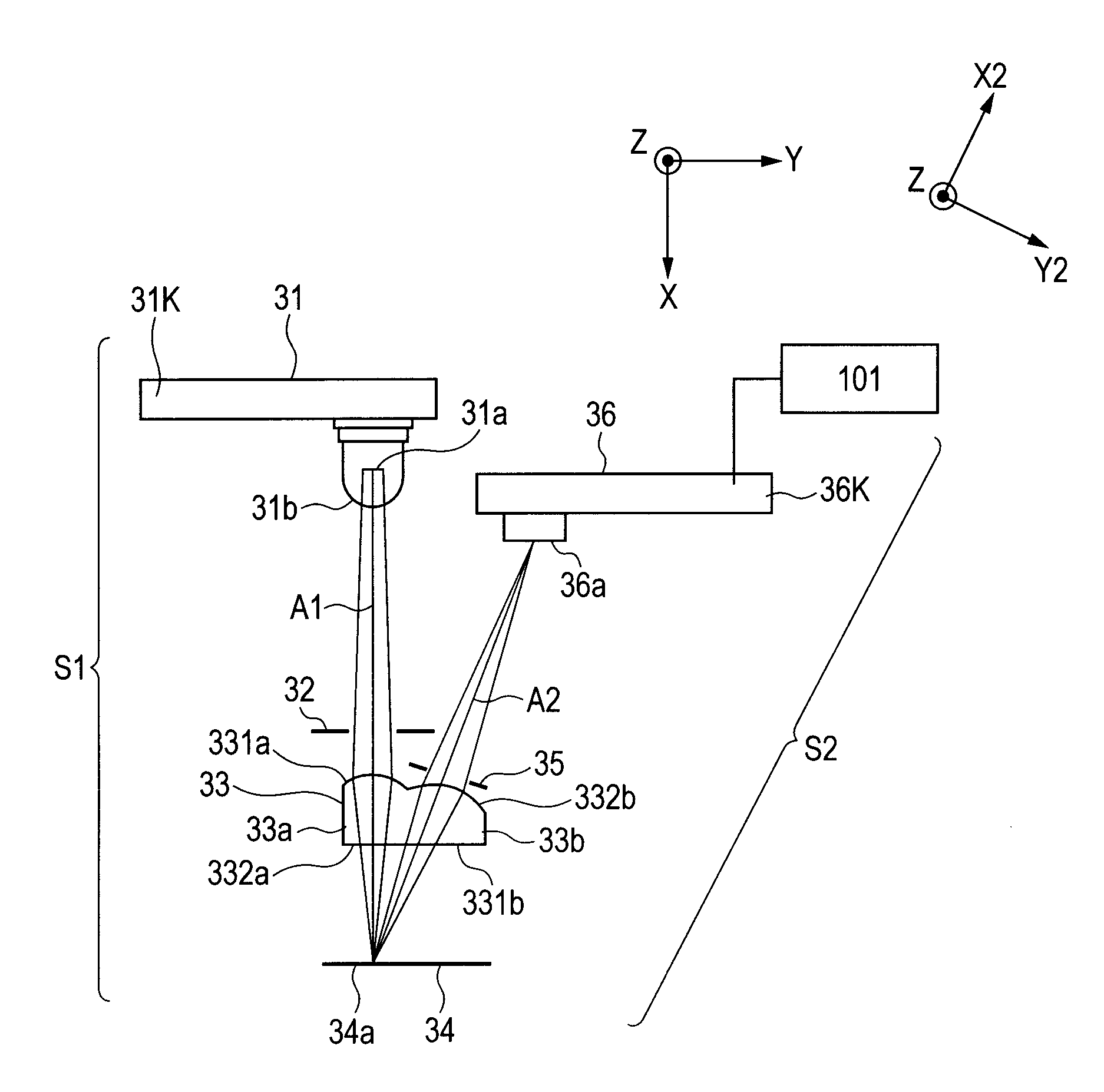
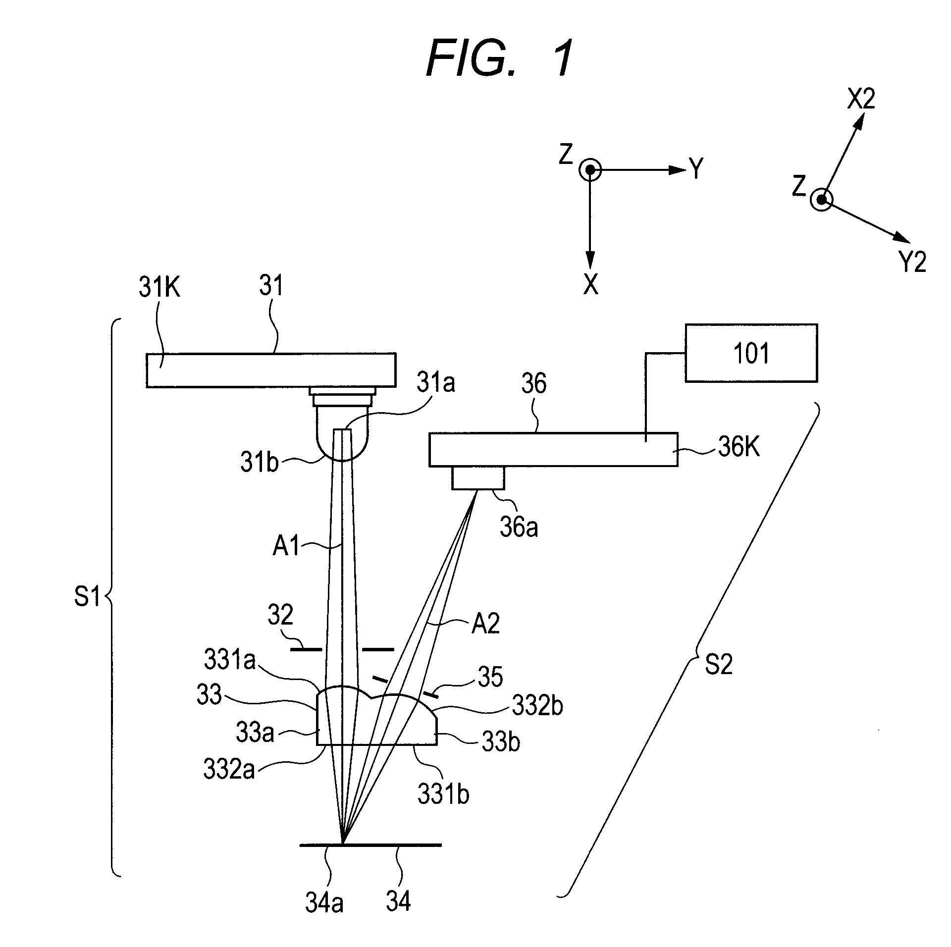
[0083]FIG. 1 is referenced again to describe Example 1. As indicated in FIG. 1, the X2-axis and the Y2-axis are introduced for the light receiving optical system S2 in the same manner as in Comparative Example 1. Example 1 is different from Comparative Example 1 in that, compared to Comparative Example 1, the surface shape of the imaging lens R2 surface (332b) is shift-decentered by 0.39 mm in the positive direction of the Y2-axis, the entire light receiving element 36 is shift-moved by 0.95 mm in the positive direction of the Y-axis.

[0084]FIG. 12 is a main scanning sectional view of the imaging optical system according to Example 1. Further, information related to the layout and surface shapes of the respective members is shown in the following Table 3. Further, the following Table 4 shows the ray passing coordinates of the principal ray on the respective surfaces.

[0085]

TABLE 3Example 1SurfaceSurface vertexvertex normalRefractivecoordinatesdirection cosineindexSurface shapeXYZαxαyα...

example 2

[0109]In order to solve the above-mentioned problem, Example 2 of the present invention obtained by taking a countermeasure against Comparative Example 2 is described below. In Example 2, a central ray of the light beam exiting from a light source unit 41 is defined as an illumination system principal ray A3. An illumination lens (illumination optical element) 33c includes at least one optical plane for refracting an illumination system principal ray. The at least one optical plane of the illumination optical element is configured so that the illumination system principal ray before passing therethrough enters the illumination optical element in a direction of becoming farther apart from the light receiving element 36 than the illumination system principal ray A3 after passing through the optical plane.

[0110]Also in this example, in the same manner as in Comparative Example 2 illustrated in FIG. 14, the light source substrate 31k for irregular reflection for detecting the color misr...


PUM


Abstract

Provided is a detecting apparatus including an illumination optical system for emitting an image bearing member with a light beam emitted from a light source unit, an imaging optical system including an imaging optical element for imaging an image on the surface of the image bearing member, a light receiving unit for detecting the image on the image bearing member which has been imaged by the imaging optical system, and a calculation unit for detecting image information on the image on the image bearing member from a detection signal received from the light receiving unit. In the detecting apparatus, at least one optical plane of the imaging optical element is configured to refract an imaging system principal ray after passing therethrough in a direction of farther becoming apart from the light source unit than the imaging system principal ray before passing through the optical plane.

Description

BACKGROUND OF THE INVENTION[0001]1. Field of the Invention[0002]The present invention relates to a detecting apparatus used for an image forming apparatus such as a copier, a printer, or a facsimile, to which an electrophotographic process or an electrostatic recording process is applied. In particular, the present invention relates to an image information detection apparatus, which is suited for detecting image information on a pattern image for position detection formed on an image bearing member.[0003]2. Description of the Related Art[0004]In a conventional image forming apparatus for obtaining a multiple color image, images having different colors are formed in multiple image forming sections, paper is conveyed by a conveyer unit such as a conveyer belt, and the images are transferred onto the paper while being overlapped, to thereby perform multiple color image formation. In a case of obtaining a full color image by performing multiple color developing, even a slight overlap po...

Claims


Application Information

Patent Timeline
Patent Type & Authority Patents(United States)
IPC IPC(8): G03G15/01G03G15/00
CPCH04N2201/04722H04N1/506G03G2215/00059H04N2201/04731G03G15/0189H04N2201/04749G03G2215/0129H04N2201/04703H04N2201/04729H04N1/047H04N1/0315G03G15/5058G03G15/0131G03G2215/0161
Inventor NAITO, YUUTA
Owner CANON KK
Why Eureka
Try Eureka