Connector

a technology of connecting rods and connectors, applied in the direction of coupling contact members, coupling device connections, coupling/insulating coupling contact members, etc., can solve the problem of difficulty in reducing the arrangement pitch p, and achieve the effect of narrowing the arrangement pitch

Active Publication Date: 2017-03-21
JAPAN AVIATION ELECTRONICS IND LTD
View PDF6 Cites 3 Cited by
  • Summary
  • Abstract
  • Description
  • Claims
  • Application Information

AI Technical Summary

Benefits of technology

[0008]The present invention has been made in order to solve the conventional problem described above and is aimed at providing a connector capable of narrowing the arrangement pitch even if the female contacts and the male contacts are alternately arranged.

Problems solved by technology

and it was difficult to decrease the arrangement pitch P.

Method used


Image

  • Connector
  • Connector
  • Connector

Examples


Embodiment Construction

[0035]An embodiment of the present invention is described below based on the appended drawings.

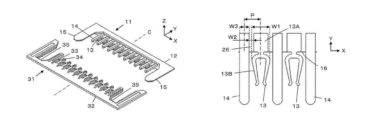
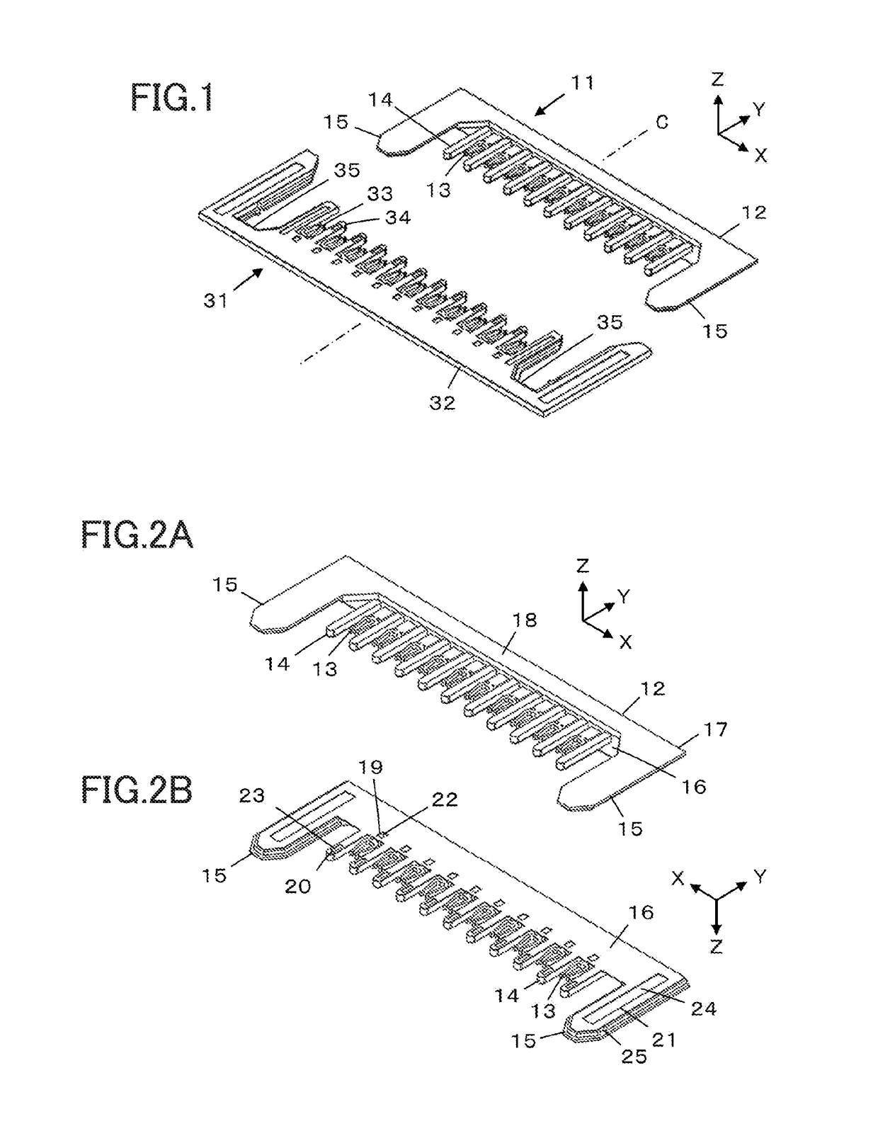
[0036]FIG. 1 illustrates a configuration of a connector according to the embodiment of the present invention. The connector comprises a flat plate first connector 11 and a flat plate second connector 31, and the first connector 11 and the second connector 31 slide on each other in a fitting direction along a fitting axis C to be fitted with each other. FIG. 1 illustrates the first connector 11 and the second connector 31 before fitting, the first connector 11 and the second connector 31 being placed in parallel with each other at an interval.

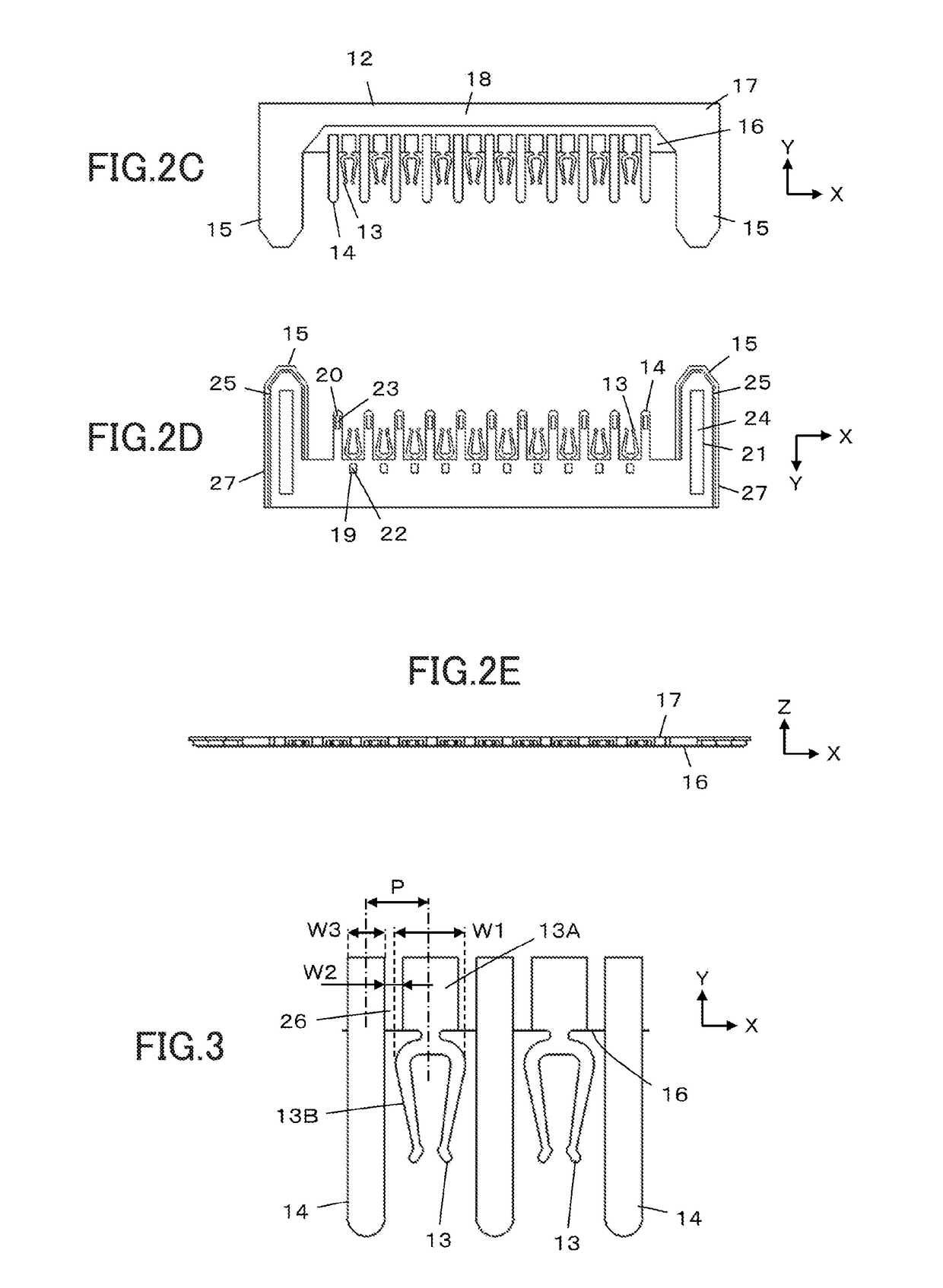
[0037]The first connector 11 includes a first connector main body 12, a plurality of first female contacts 13 and a plurality of first male contacts 14, the first connector main body 12 extending in a direction orthogonal to the fitting axis C, and the plurality of first female contacts 13 and the plurality of first male contacts 14 being held by the f...


PUM


Abstract

A connector includes a first connector having first female contacts, first male contacts and a first insulation portion disposed between each first female contact and an adjacent first male contact, and a second connector having second female contacts, second male contacts and a second insulation portion disposed between each second female contact and an adjacent second male contact, provided that a width of each first female contact and second female contact on fitting is denoted by W1, a width of the first insulation portion and the second insulation potion by W2, and a width of each first male contact and second male contact by W3, a distance between centers of one first female contact and an adjacent first male contact and a distance between centers of one second female contact and an adjacent second male contact are each smaller than a sum of W1 / 2, W2 and W3 / 2.

Description

BACKGROUND OF THE INVENTION[0001]The present invention relates to a connector, in particular, to a connector comprising a first connector and a second connector, the first connector and the second connector sliding on each other in a fitting direction to be fitted with each other.[0002]As a connector of this type, for example, JP 4-308674 A discloses a connector as illustrated in FIG. 13. The connector connects a pair of electronic circuit boards 1A and 1B to each other and comprises a first connector 2A mounted on one electronic circuit board 1A of the pair of electronic circuit boards and a second connector 2B mounted on the other electronic circuit board 1B.[0003]The first connector 2A has a structure in which a plurality of female contacts 4A and a plurality of male contacts 5A are alternately arranged in an arrangement direction R in a housing 3A made from an insulator. Each of the female contacts 4A has its full length in a fitting direction enclosed by the housing 3A, and eac...

Claims


Application Information

Patent Timeline
Patent Type & Authority Patents(United States)
IPC IPC(8): H01R25/00H01R24/60H01R13/04H01R13/10H01R13/631H01R107/00
CPCH01R24/60H01R13/04H01R13/10H01R13/631H01R2107/00H01R12/7011H01R12/718H01R13/035H01R13/112H01R13/40H01R13/6273H01R12/7005H01R12/732H01R24/84
Inventor KOMOTO, TETSUYATATEBE, YU
Owner JAPAN AVIATION ELECTRONICS IND LTD
Why Eureka
Try Eureka