Bioactive fusion device

a bioactive fusion and system technology, applied in the field of bioactive systems, can solve the problems of not always clinically successful use of dynamic systems, failure of instruments and the need for revision surgery, and defeat the attempt to limit reoperations, so as to reduce the amount of slippage and reoperation, reduce the amount of medical costs, and reduce the effect of minimal invasiveness

Active Publication Date: 2017-11-07
UNIVERSITY OF TOLEDO
View PDF22 Cites 4 Cited by
  • Summary
  • Abstract
  • Description
  • Claims
  • Application Information

AI Technical Summary

Benefits of technology

[0009]An advantage of the fusion device is reduced medical costs from a less invasive surgical procedure. Another advantage is the reduced amount of slippage and re-operations that are required. A further advantage is the achievement of comparable stabilization of the spine with minimal invasiveness.

Problems solved by technology

However, there are recent reports of instrumentation failures and the need for revision surgery.
Thus, the uses of dynamic systems are not always clinically successful and may defeat the attempt to limit reoperations.

Method used


Image

  • Bioactive fusion device
  • Bioactive fusion device
  • Bioactive fusion device

Examples


first embodiment

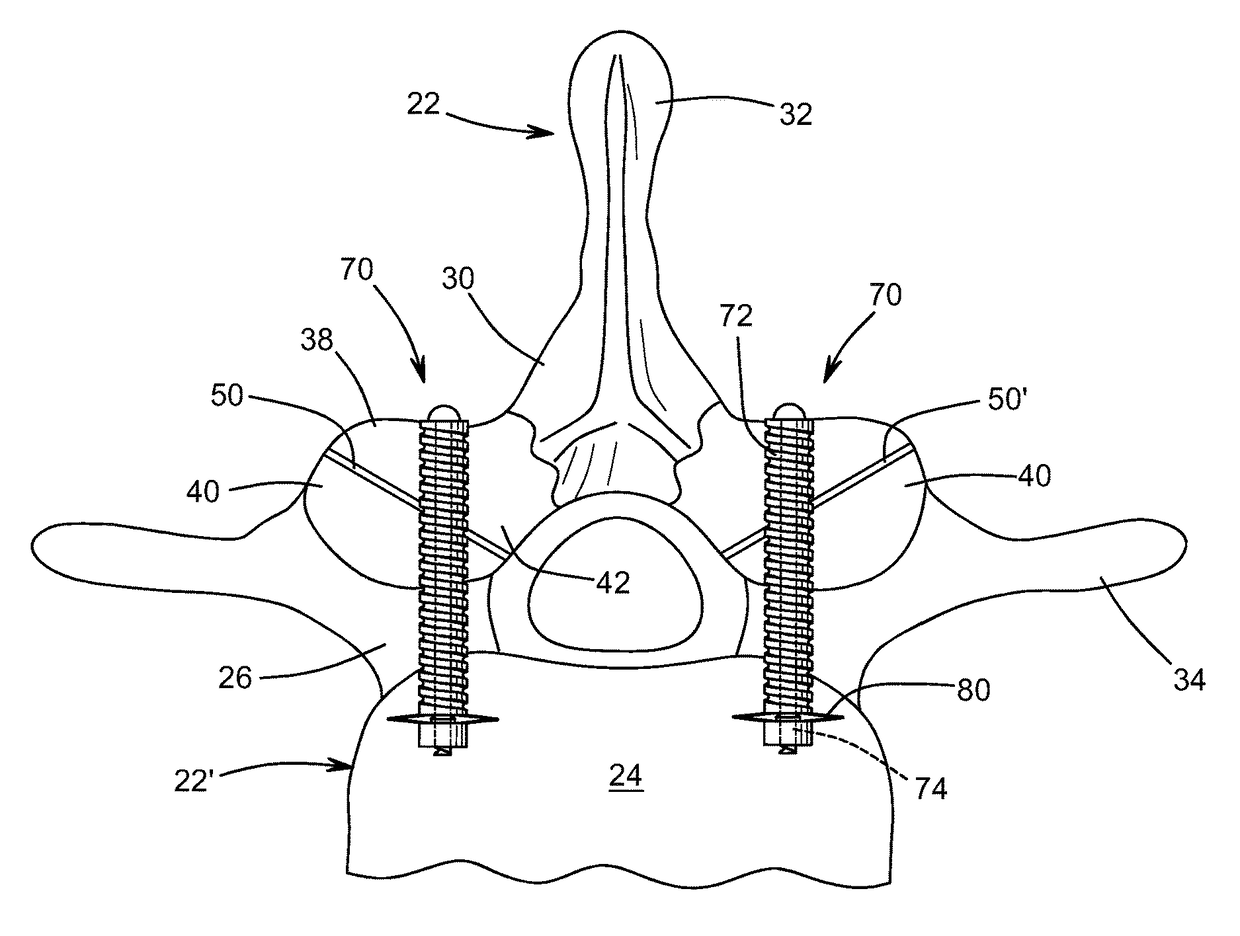
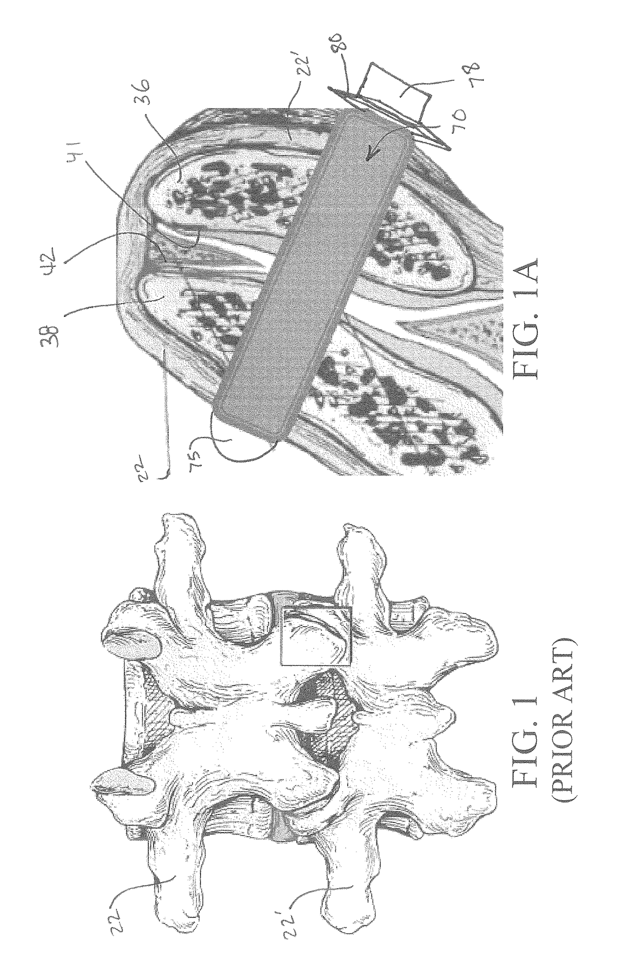
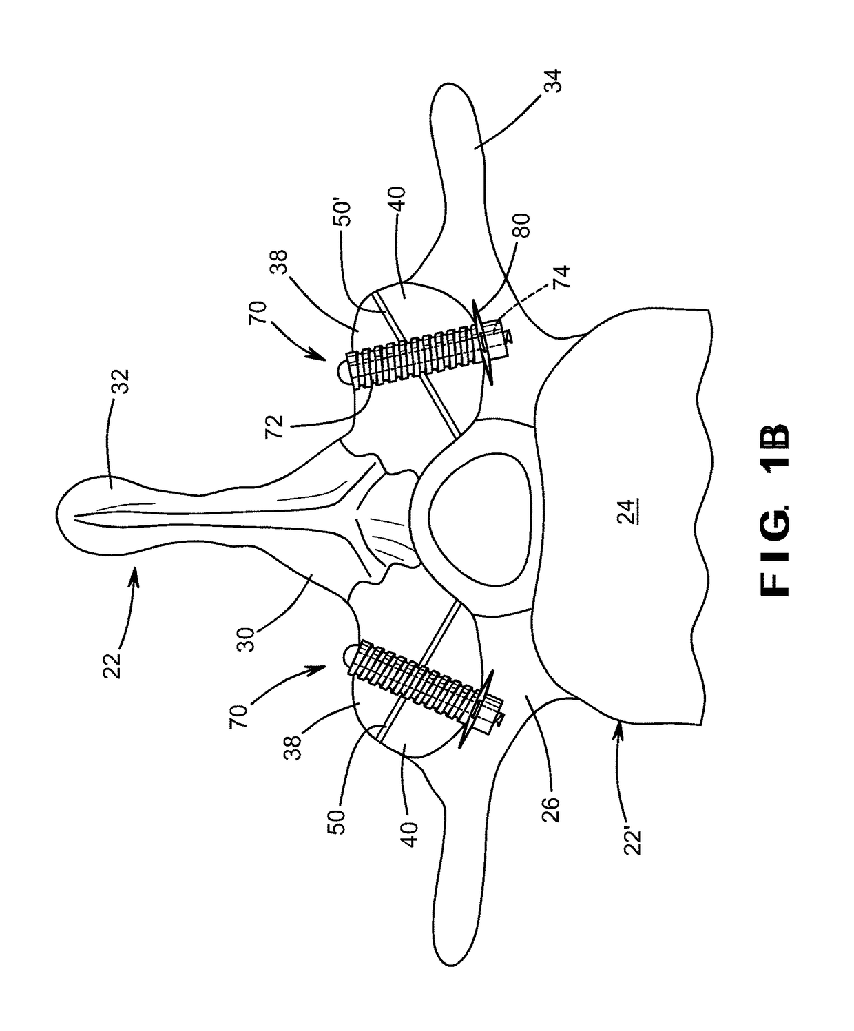
[0033]As shown in various embodiments in FIGS. 1A, 1B, and 1C, a fusion device 70 includes a hollow bone dowel portion 72. The illustrated hollow bone dowel portion 72 is internally threaded for at least a distal portion of its length, although such is not required. A bone screw portion 74 of the fusion device 70 can be disposed within the hollow bone dowel portion 72. For example, the bone screw portion 74 of the fusion device 70 can be externally threaded and be threaded within the hollow bone dowel portion 72. The screw portion 74 of the fusion device 70 can be formed from any desired material including, for example, a metallic material such as titanium. As shown in FIG. 2, the screw portion 74 of the fusion device 70 can be formed from a solid body of material having an external helical thread or other similar structure provided thereon. Alternatively, as shown in FIG. 3, the screw portion 74 can be formed from a ribbon of material having a helical or other similar shape.

[0034]T...

second embodiment

[0042]FIGS. 11 through 13 illustrate a fusion device, indicated generally at 100, in accordance with this invention. As shown therein, the fusion device 100 includes a screw portion 101 having a first externally threaded portion 102 and a second externally threaded portion 103. The screw portion 101 may be formed from any desired material, including that described above in connection with the bone screw 74. The fusion device 100 also includes a hollow bone dowel portion 104 that, when assembled, extends about the screw portion 101. The bone dowel portion 104 may include an internally threaded portion (not shown) that engages the second externally threaded portion 103 of the screw portion 101, although such is not required. The fusion device 100 further includes a head portion 105 having an internally threaded portion (not shown) that engages the second externally threaded portion 103 of the screw portion 101. As a result, the hollow bone dowel portion 104 is retained about the screw...


PUM


Abstract

In a first broad aspect, there is provided herein a bioactive device and system for fusion between two bones, two parts of a bony joint, or a bony defect, such as of the spine. The fusion device includes a screw having a head and a threaded shaft. The fusion device also includes a bone dowel having an internal bore of which at least a distal portion is threaded to engage the threads of the screw shaft. The bone dowel is made of a bone-like, biocompatible, or allograft material to provide a layer of bone-like, biocompatible, or allograft material between the screw and the spinal bone. The device is generally coaxial and is further described in the drawings and description herein.

Description

CROSS-REFERENCE TO RELATED APPLICATIONS[0001]This application claims the benefit of U.S. Provisional Application No. 61 / 593,270, filed Jan. 31, 2012, the disclosure of which is incorporated herein by reference.STATEMENT REGARDING FEDERALLY SPONSORED RESEARCH[0002]The invention was not made with government support, and the government has no rights in the invention.TECHNICAL FIELD AND INDUSTRIAL APPLICABILITY[0003]This invention relates, in part, to a bioactive system for fusion between two bones, two parts of a bony joint, or a bony defect, such as of the spine. This invention also relates, in part, to methods of making and methods of using such a bioactive system for fusion.BACKGROUND OF THE INVENTION[0004]Over 650,000 spine surgeries are performed annually in the United States, with the majority being decompressive laminectomies for spinal stenosis. Spinal stenosis is a narrowing of the spinal canal housing the spinal cord, which is generally caused by arthritis of articulating bon...

Claims


Application Information

Patent Timeline
Patent Type & Authority Patents(United States)
IPC IPC(8): A61B17/86A61F2/44A61B17/70A61B17/56
CPCA61B17/866A61B17/7064A61B17/8625A61F2/442A61F2/4455A61B17/8685A61F2/446A61B2017/564
Inventor GOEL, VIJAY K.AGARWAL, ANAND K.
Owner UNIVERSITY OF TOLEDO
Why Eureka
Try Eureka