Air conditioning system

a technology of air conditioning system and air conditioner, which is applied in the field of air conditioning system, can solve the problems of slow indoor temperature drop, and high cost of operation, and achieves the effect of fast switch from heat pump air-warming operation to separate heat source air-warming operation

Active Publication Date: 2018-03-27
DAIKIN IND LTD
View PDF24 Cites 1 Cited by
  • Summary
  • Abstract
  • Description
  • Claims
  • Application Information

AI Technical Summary

Benefits of technology

[0005]An object of the present invention is to make the switch timing appropriate and improve the comfort level and the energy conservation when the operation is switched from the heat pump air-warming operation to the separate heat source air-warming operation in an air conditioning system comprising the heat pump section and the separate heat source section.
[0008]It is thereby possible in this aspect for the switch from the heat pump air-warming operation to the separate heat source air-warming operation to be made at an appropriate timing, and for the comfort level and energy conservation to be improved.
[0011]It is thereby possible in this aspect for the switch from the separate heat source air-warming operation to the heat pump air-warming operation to be made at an appropriate timing, and for the comfort level and the energy conservation to be improved.

Problems solved by technology

With the method of switching from the heat pump air-warming operation to the separate heat source air-warming operation in the aforementioned Japanese Laid-open Patent Application No. 64-54160, there is a risk that the switch from the heat pump air-warming operation to the separate heat source air-warming operation will be slow and an indoor temperature will drop when the indoor air-conditioning load (air-warming load) is large, and there is a risk that the switch from the heat pump air-warming operation to the separate heat source air-warming operation will be fast and an energy conservation will be impaired when the indoor air-conditioning load (air-warming load) is small.
By contrast, it is conceivable to appropriately set the outside air temperature at which the operation will be switched from the heat pump air-warming operation to the separate heat source air-warming operation in accordance with factors such as the installation conditions of the air conditioning system, but this setting would not be easy and the working man-hours would increase.

Method used


Image

  • Air conditioning system
  • Air conditioning system
  • Air conditioning system

Examples


Embodiment Construction

[0033]An embodiment of an air conditioning system according to the present invention is described below on the basis of the drawings. The specific configuration of the embodiment of the air conditioning system according to the present invention is not limited to the following embodiment or the modifications thereof, and the configuration can be altered within a range that does not deviate from the scope of the invention.

[0034](1) Configuration of Air Conditioning System

[0035]

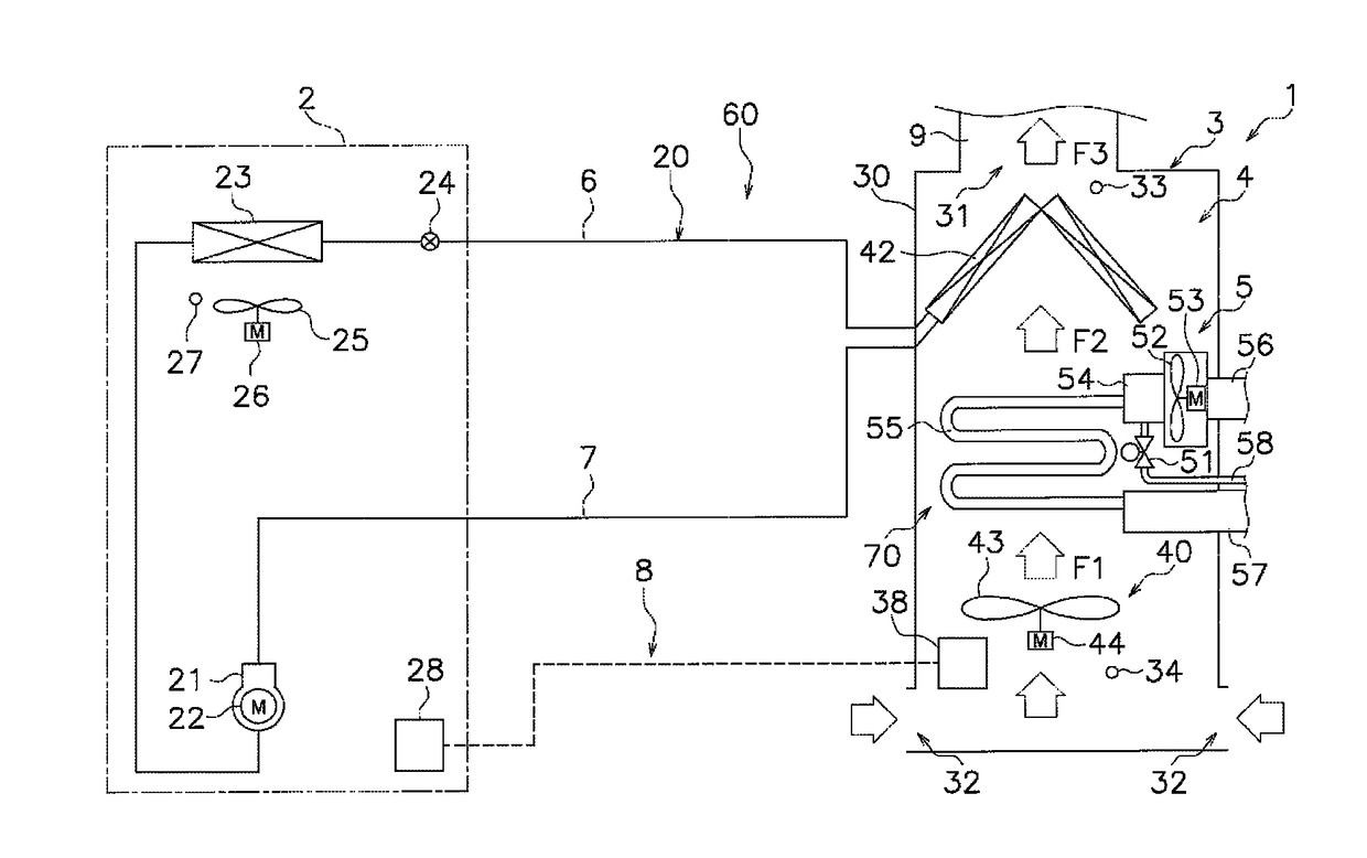
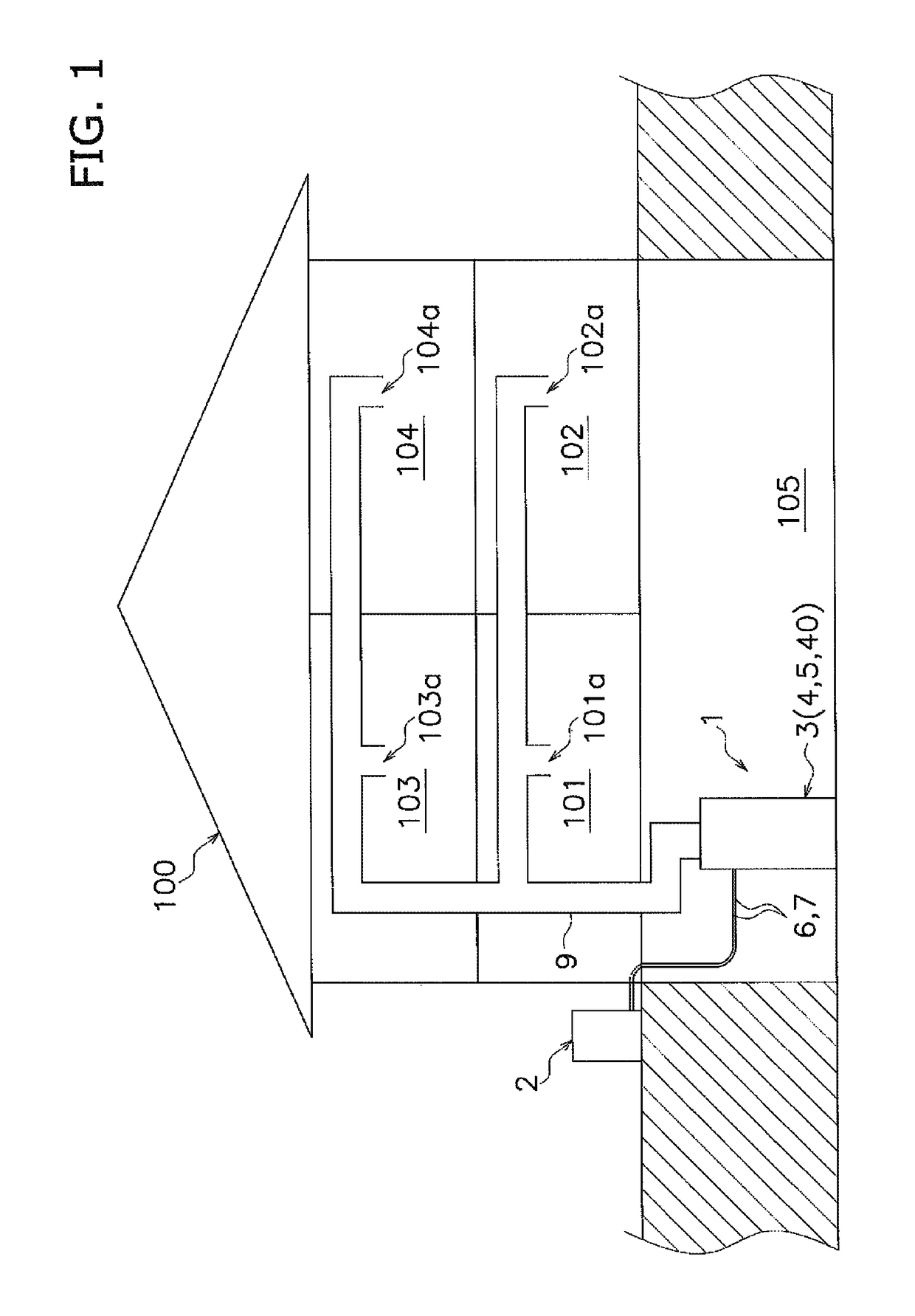
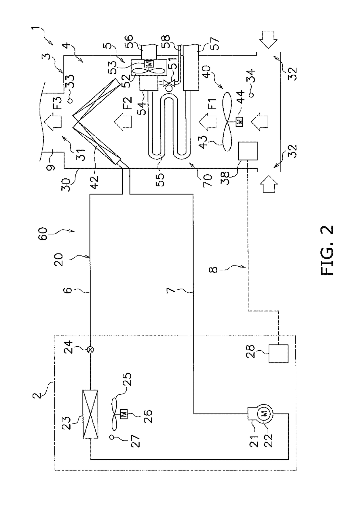
[0036]FIG. 1 is a schematic diagram showing the arrangement of an air conditioning system 1 according to an embodiment of the present invention. FIG. 2 is a simplified schematic diagram of the air conditioning system 1. The air conditioning system 1 is an apparatus used to air-condition a residence or a building. The air conditioning system 1 in this embodiment is installed in a two-story residence 100. The residence 100 has rooms 101, 102 on the first floor and rooms 103, 104 on the second floor. The residence ...


PUM


Abstract

An air conditioning system includes a heat pump section performing indoor air-warming by using a vapor-compression refrigeration cycle, a separate heat source section performing indoor air-warming by using a heat source separate from the heat pump section, and a control unit configured to control actions of the heat pump section and the separate heat source section. When a heat pump air-warming operation is being performed, and when a first switching condition is met, the control unit switches from the heat pump air-warming operation to a separate heat source air-warming operation. The first switching condition is that an outside air temperature reaches a first switching outside air temperature and an air-warming capability of the heat pump section reaches an upper limit.

Description

CROSS-REFERENCE TO RELATED APPLICATIONS[0001]This U.S. National stage application claims priority under 35 U.S.C. § 119(a) to Japanese Patent Application No. 2014-018778, filed in Japan on Feb. 3, 2014, the entire contents of which are hereby incorporated herein by reference.TECHNICAL FIELD[0002]The present invention relates to an air conditioning system, and particularly relates to an air conditioning system having a heat pump section for performing indoor air-warming by using a vapor-compression refrigeration cycle, and a separate heat source section for performing indoor air-warming by using a heat source separate from the heat pump section.BACKGROUND ART[0003]In the past, there have been air conditioning systems which have a heat pump section for performing indoor air-warming by using a vapor-compression refrigeration cycle, and a separate heat source section for performing indoor air-warming by using a gas furnace which is a heat source separate from the heat pump section. An e...

Claims


Application Information

Patent Timeline
Patent Type & Authority Patents(United States)
IPC IPC(8): F24D12/02F24D15/04F24F11/00F24F3/00F24D15/02F24D19/10F24D5/12
CPCF24F11/62F24D19/1087F24D12/02F24D15/02F24D15/04F24F3/001Y02B30/14F24F2110/12F24F11/65F24D2200/04F24D2200/123F24D2200/32Y02B30/12Y02B30/123F24F11/30F24F11/46Y02B30/00F24F11/84F24F11/63F24H15/345F24H15/31F24H15/204F24H15/208F24H15/38F24H15/421F24H15/385F24H15/176F24H15/258F24H15/36
Inventor KOJIMA, AKIHARU
Owner DAIKIN IND LTD
Why Eureka
Try Eureka