
Hot-Runner System having Non-Structurally Supportive Heat Insulator Including Visible Material

Inactive Publication Date: 2012-03-08
HUSKY INJECTION MOLDING SYST LTD
View PDF3 Cites 1 Cited by
  • Summary
  • Abstract
  • Description
  • Claims
  • Application Information

AI Technical Summary

Benefits of technology

[0010]The inventors believe that the problem associated with known hot-runner systems is not understood by persons skilled in the art of molding system and hot-runner systems; due to the high cost of energy associated with operating hot-runner systems, the inventors believe known heat insulators must be improved, and in this manner energy conservation is improved; more specifically, the inventors believe that what is required is a heat insulator that works better than the heat-insulating ability of air, and this new arrangement will mitigate, at least in part, the drawbacks associated with operating costs associated with the known hot-runner systems.
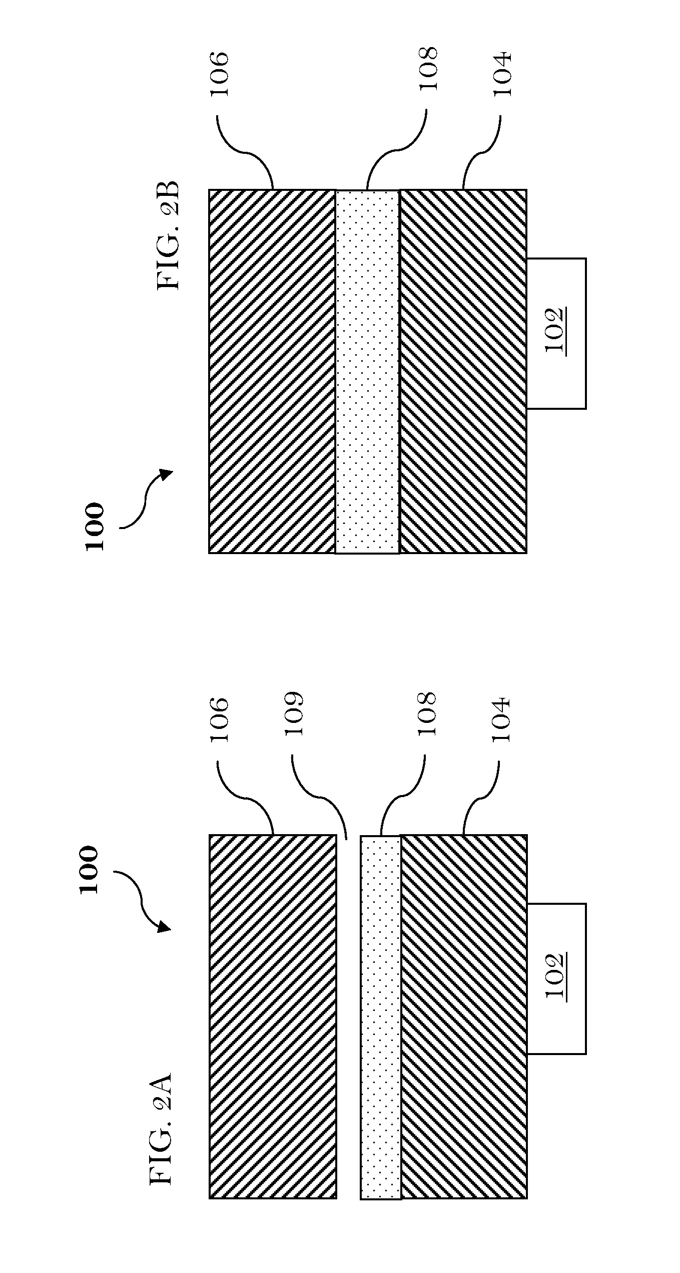
[0012]According to a second aspect of the present invention, there is provided a hot-runner system configured for use with a molding system. The hot-runner system includes a heater configured to generate thermal energy responsive to receiving power. The hot-runner system also includes a heat-sourcing component configured to receive the thermal energy from the heater, so that the thermal energy that is generated by the heater is transferred, at least in part, from the heater to the heat-sourcing component, and the heat-sourcing component becomes heated to an operating temperature. The hot-runner system also includes a heat-receiving component that is at least partially spaced from the heat-sourcing component. The operating temperature of the heat-receiving component is cooler than the operating temperature of the heat-sourcing component. The hot-runner system also includes a non-structurally supportive heat insulator including a visible material. The visible material is temperature compatible with the heat-sourcing component. The visible material has a thermal conductivity that is lower than the thermal conductivity of air during operation of the hot-runner system, whereby, in use, the non-structurally supportive heat insulator: (i) reduces heat transmission from the heat-sourcing component to the heat-receiving component, and (ii) permits reduction of power consumption of the heater.

Problems solved by technology

It will be appreciated that these types of known heat insulators are relatively inefficient in comparison to using an air gap between the known components.
The air gap is also a known heat insulator, but unfortunately the air gap permits the following drawbacks: (i) heat convection between the known components, and (ii) heat radiation transmitted between the known components when the known components are operated at respectively different temperatures.

Method used


Image

  • Hot-Runner System having Non-Structurally Supportive Heat Insulator Including Visible Material
  • Hot-Runner System having Non-Structurally Supportive Heat Insulator Including Visible Material
  • Hot-Runner System having Non-Structurally Supportive Heat Insulator Including Visible Material

Examples


Embodiment Construction

)

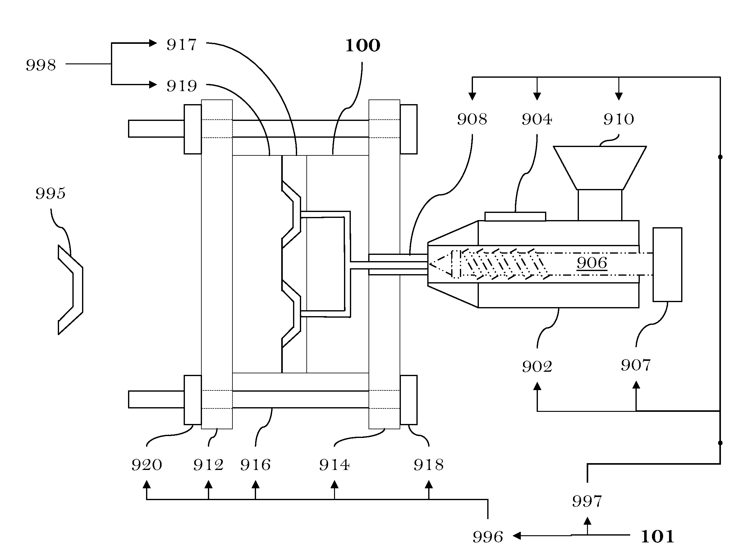
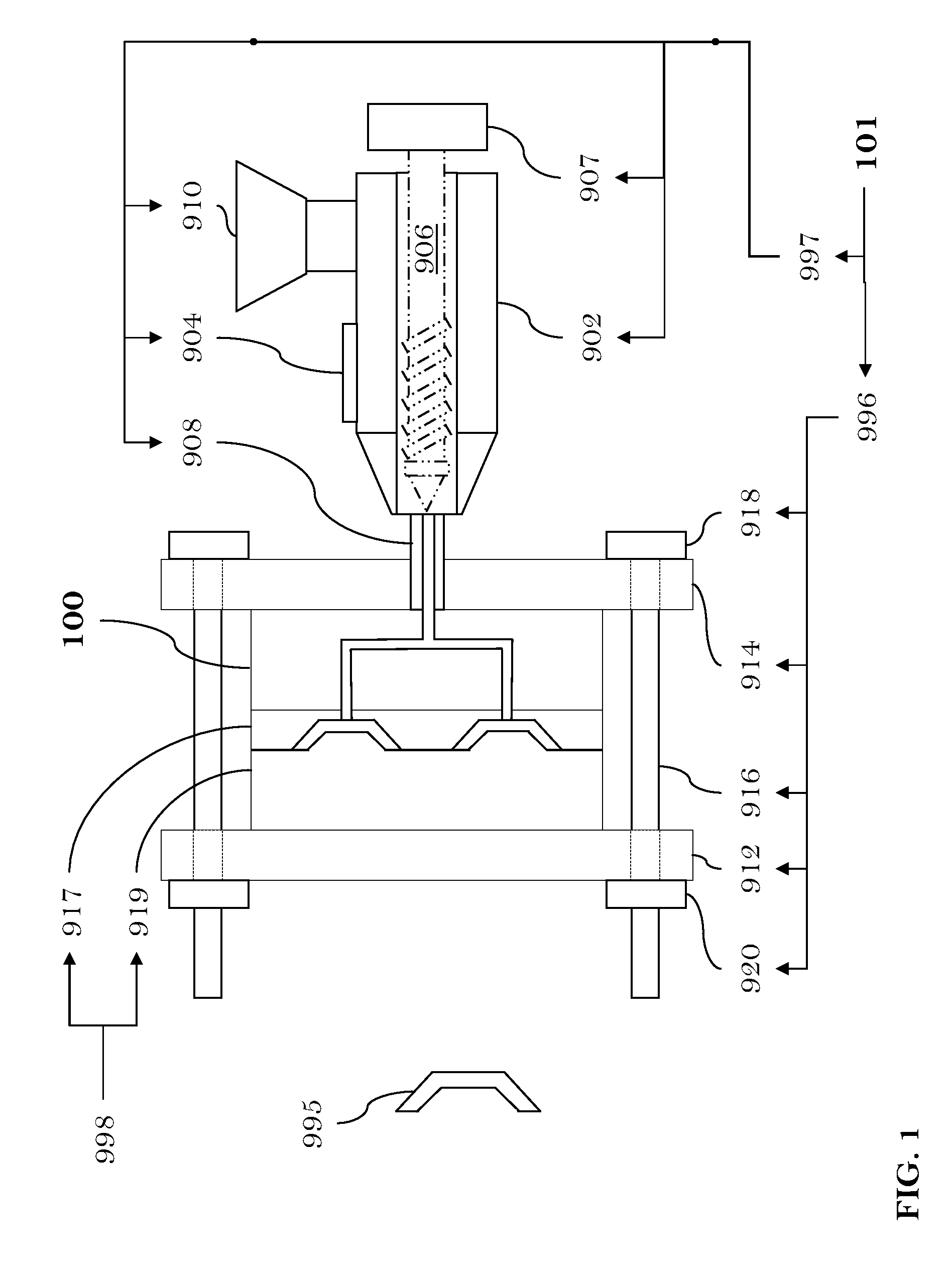
[0053]FIG. 1 depicts the schematic view, at least in part, of the HR system 100 and the molding system 101 according to the first non-limiting embodiment. The HR system 100 is configured for use with the molding system 101 (such as, an injection-molding system, etc). It will be appreciated that the HR system 100 and the molding system 101 may include components (and sub-systems) that are known to persons skilled in the art, and as such these known components will not be described in this document. A description of the known components and known sub-systems is provided, at least in part, with sufficient details in the following reference books: (i) “Injection Molding Handbook” authored by OSSWALD / TURNG / GRAMANN (ISBN: 3-446-21669-2), (ii) “Injection Molding Handbook” authored by ROSATO AND ROSATO (ISBN: 0-412-99381-3), (iii) “Injection Molding Systems” (Third Edition) authored by JOHANNABER (ISBN 3-446-17733-7) and / or (iv) “Runner and Gating Design Handbook” authored by BEAUMONT (ISB...


PUM

PropertyMeasurementUnit
Temperatureaaaaaaaaaa
Flow rateaaaaaaaaaa
Pore structureaaaaaaaaaa

Abstract

Hot-runner system (100) for use with molding system. Hot-runner system (100) having: heater (102) to generate heat responsive to receiving power. Heat-sourcing component (104) to receive heat from the heater (102) so that the heat that is generated by the heater (102) is transferred, at least in part, from heater (102) to heat-sourcing component (104). Heat-sourcing component (104) becomes heated to an operating temperature. Heat-receiving component (106) being at least partially spaced from the heat-sourcing component (104). The operating temperature of the heat-receiving component (106) being cooler than operating temperature of the heat-sourcing component (104). Non-structurally supportive heat insulator (108) has thermal conductivity being lower than thermal conductivity of air during operation of the hot-runner system (100). Whereby, in use, non-structurally supportive heat insulator (108): (i) reduces heat transmission from heat-sourcing component (104) to heat-receiving component (106), and (ii) permits reduction of power consumption of heater (102).

Description

TECHNICAL FIELD[0001]The present invention generally relates to, but is not limited to, hot-runner systems for use with molding systems, and more specifically the present invention relates to, but is not limited to a hot-runner system configured for use with a molding system, the hot-runner system has an insulator that includes a visible material, and the visible material has a thermal conductivity being lower than the thermal conductivity of air.BACKGROUND OF THE INVENTION[0002]Examples of known molding systems are (amongst others): (i) the HYPET™ Molding System, (ii) the QUADLOC™ Molding System, (iii) the HYLECTRIC™ Molding System, and (iv) the HYMET™ Molding System, all manufactured by HUSKY INJECTION MOLDING SYSTEMS LIMITED (location: Ontario, Canada).[0003]Known insulating materials (also called “heat insulators”) are placed or located between components of known hot-runner systems, such as: a hot-runner manifold and a cooled mold plate. The following are examples of known heat...

Claims


Application Information

Patent Timeline
IPC IPC(8): F28F7/00
CPCB29C45/2737B29C2045/2795B29C2033/023B29C45/2738
Inventor DEZON-GAILLARD, PATRICE FABIENBLAIS, PAULJENKO, EDWARD JOSEPH
Owner HUSKY INJECTION MOLDING SYST LTD
Learn More