Check patentability & draft patents in minutes with Patsnap Eureka AI!

Durability test device of membrane electrode assembly and durability test method thereof

a technology of durability test and membrane electrode, which is applied in the direction of fuel cell, primary cell maintainance/servicing, electrical apparatus, etc., can solve the problems of reduced production efficiency, increased test facility, and damage to the membrane electrode, so as to shorten the test period , the effect of reducing the peak value of curren

Active Publication Date: 2018-05-29
TOYOTA JIDOSHA KK
View PDF8 Cites 0 Cited by
  • Summary
  • Abstract
  • Description
  • Claims
  • Application Information

AI Technical Summary

Benefits of technology

[0009]According to the durability test device, since the first sweep rate of the voltage to be applied in the first voltage region that includes the peak caused due to carbon oxidation is set lower than the second sweep rate in the second voltage region, it is possible to decrease a peak value of the current caused due to the carbon oxidation in comparison with a case where the voltage is applied in the first voltage region at the same sweep rate as the second voltage region that does not include the first voltage region. Note that, when the second sweep rate of the voltage in the second voltage region is set faster than the first sweep rate in the first voltage region, it is possible to shorten a test period. Accordingly, it is possible to shorten the test period and to lower the peak value of the current due to the carbon oxidation.
[0011]A current flowing due to electrolysis of water is smaller than the peak value of the current caused due to the carbon oxidation. Accordingly, even if the second sweep rate in the second voltage region that includes the peak caused due to electrolysis of water is set higher than that of the first voltage region, the peak value of the current caused due to electrolysis is measurable. According to the durability test device, since the second sweep rate of the voltage in the second voltage region is set higher than that of the first voltage region, it is possible to shorten the test period.
[0013]According to the durability test device, since the sweep rates of the voltage in the second and third voltage regions is set higher than that of the first voltage region, it is possible to shorten the test period.
[0015]The peak value of the current caused due to the carbon oxidation appears in the voltage region where the applied voltage is larger than 2 V but smaller than 3 V. According to the durability test device configured as such, it is possible to lower the peak value of the current caused due to the carbon oxidation.
[0017]According to the durability test method, since the first sweep rate of the voltage to be applied in the first voltage region that includes the peak caused due to carbon oxidation is set lower than the second sweep rate of the voltage in the second voltage region, it is possible to decrease the peak value of the current caused due to the carbon oxidation in comparison with a case where the voltage is applied in the first voltage region at the same sweep rate as the second voltage region that does not the first voltage region. Note that, when the second sweep rate of the voltage in the second voltage region is set faster than the sweep rate in the first voltage region, it is possible to shorten a test period. Accordingly, it is possible to shorten the test period and to lower the peak value of the current caused due to the carbon oxidation.
[0018]According to such aspects, it is possible to achieve at least one of various objects of cost reduction, resource saving, simplification of manufacture, improvement in performance, and the like.

Problems solved by technology

However, in consideration of such a case where the MEA as a test object is used as a product after the durability test, if a test period is long, the MEA may be damaged, which would be a problem.
Further, in consideration of mass production of the membrane electrode assembly MEA, if a test period is long, productive efficiency decreases, which would be a problem.
However, in order to measure such a large current value due to the carbon oxidation peak, test facility is upsized and a cost is increased, which would be a problem.

Method used


Image

  • Durability test device of membrane electrode assembly and durability test method thereof
  • Durability test device of membrane electrode assembly and durability test method thereof
  • Durability test device of membrane electrode assembly and durability test method thereof

Examples


Embodiment Construction

[0025]A. First Embodiment:

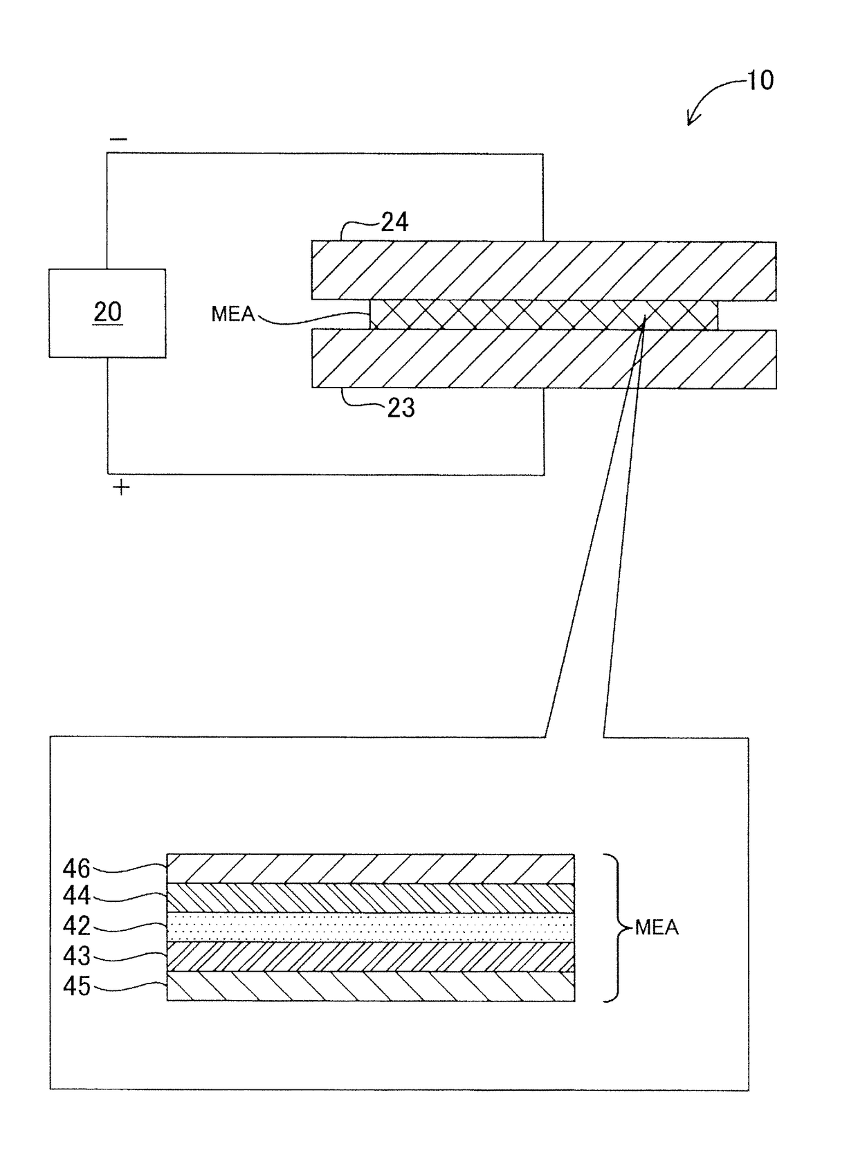
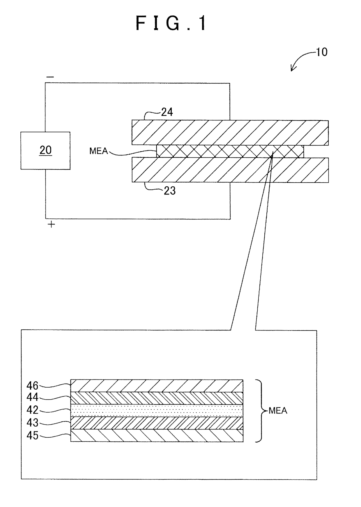
[0026](A1) Durability Test Device: FIG. 1 is a schematic view illustrating a configuration of a durability test device 10 as a first embodiment of the present invention. The durability test device 10 is a device for examining durability of a membrane electrode assembly MEA used for a fuel cell by applying a voltage to the membrane electrode assembly MEA while sweeping the voltage in a predetermined voltage region.

[0027]The durability test device 10 includes a measurement control section 20, a positive electrode 23, and a negative electrode 24. The positive electrode 23 and the negative electrode 24 are electrically connected to the measurement control section 20. The measurement control section 20 applies a voltage between the positive electrode 23 and the negative electrode 24, and measures a current flowing between the electrodes. The measurement control section 20 can sweep a voltage to be applied between the electrodes in a predetermined voltage region....


PUM

PropertyMeasurementUnit
voltageaaaaaaaaaa
voltageaaaaaaaaaa
applied voltageaaaaaaaaaa

Abstract

A durability test device that examines durability of a membrane electrode assembly used for a polymer electrolyte fuel cell includes: a voltage application device that applies a voltage from one surface of the membrane electrode assembly to the other surface thereof; a current measurement device that measures a current flowing from the one surface to the other surface by the application of the voltage; and a control section that controls the voltage application device to apply the voltage to the membrane electrode assembly while sweeping the voltage over a plurality of consecutive voltage regions in such a manner that a first sweep rate of the voltage to be applied in the first voltage region in which a measured current value includes a peak caused due to carbon oxidation is set lower than that in the second voltage region that does not include the first voltage region.

Description

INCORPORATION BY REFERENCE[0001]The disclosure of Japanese Patent Application No. 2013-222075 filed on Oct. 25, 2013 including the specification, drawings and abstract is incorporated herein by reference in its entirety.BACKGROUND OF THE INVENTION[0002]1. Field of the Invention[0003]The present invention relates to a technique to examine durability of a membrane electrode assembly used for a polymer electrolyte fuel cell.[0004]2. Description of Related Art[0005]As a method for examining durability of a polymer electrolyte fuel cell, there has been known a technique described in Japanese Patent Application Publication No. 2006-120545 (JP 2006-120545 A), for example. JP 2006-120545 A describes a method for evaluating accelerated deterioration of an electrolyte membrane. In the evaluation method, an electrolyte membrane is provided in a container in which an aqueous electrolyte is poured, as a diaphragm that divides the aqueous electrolyte into two, and a positive electrode is provided...

Claims


Application Information

Patent Timeline
Patent Type & Authority Patents(United States)
IPC IPC(8): H01M6/50H01M8/1004H01M8/1018
CPCH01M6/5083H01M2008/1095H01M8/1004Y02E60/50
Inventor ODA, TOHRUKINOSHITA, KATSUHIKOKAWAHARA, TATSUYA
Owner TOYOTA JIDOSHA KK
Features
  • R&D
  • Intellectual Property
  • Life Sciences
  • Materials
  • Tech Scout
  • Unparalleled Data Quality
  • Higher Quality Content
  • 60% Fewer Hallucinations
Learn More