
Tracking aspiration catheter
Patent Information
- Authority / Receiving Office
- US · United States
- Current Assignee / Owner
- Publication Date
- 2007-03-15
Smart Images
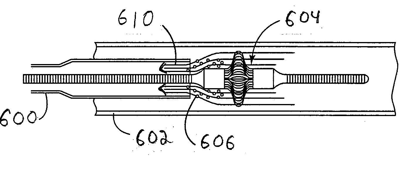
Figure 1 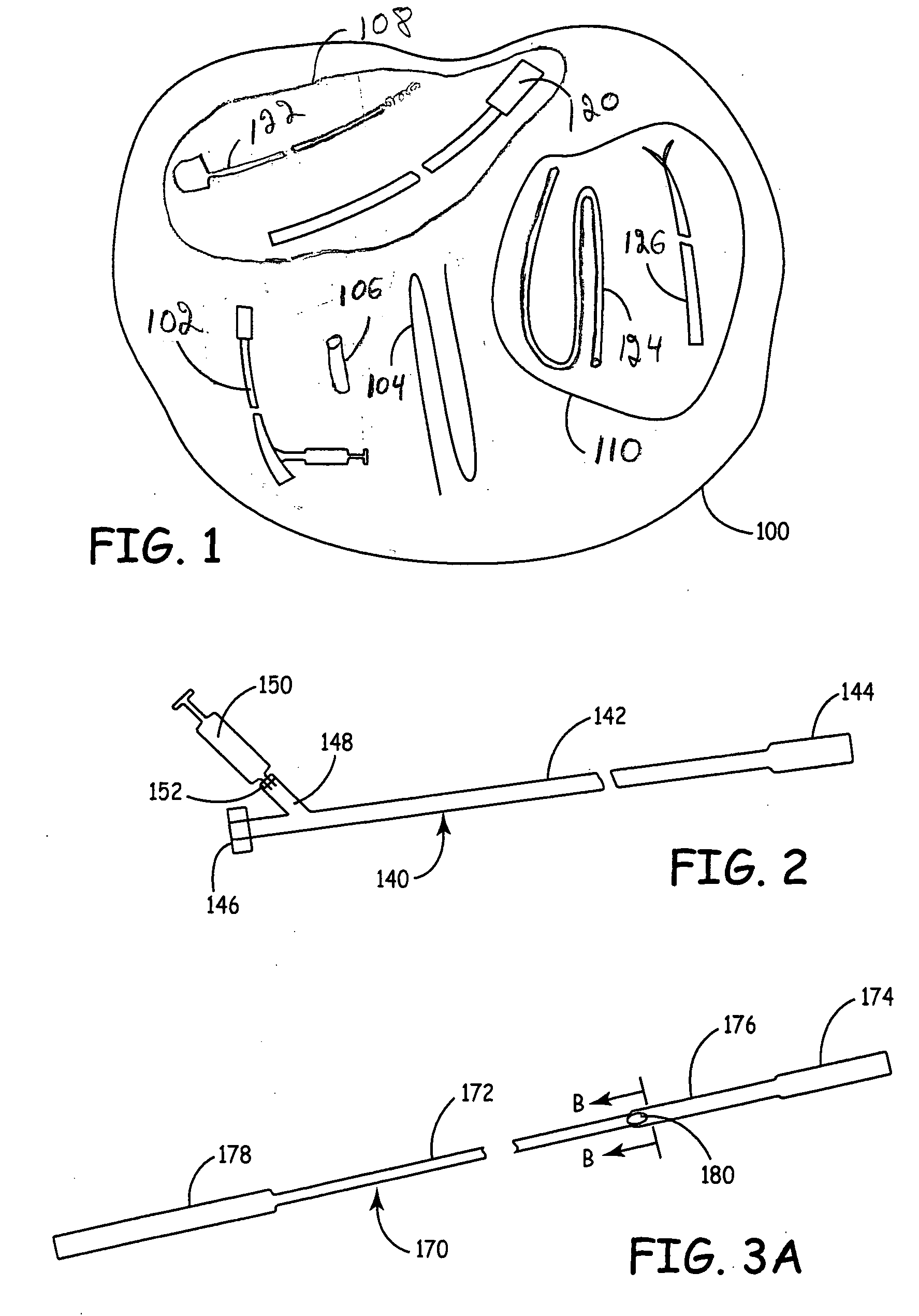
Figure 2 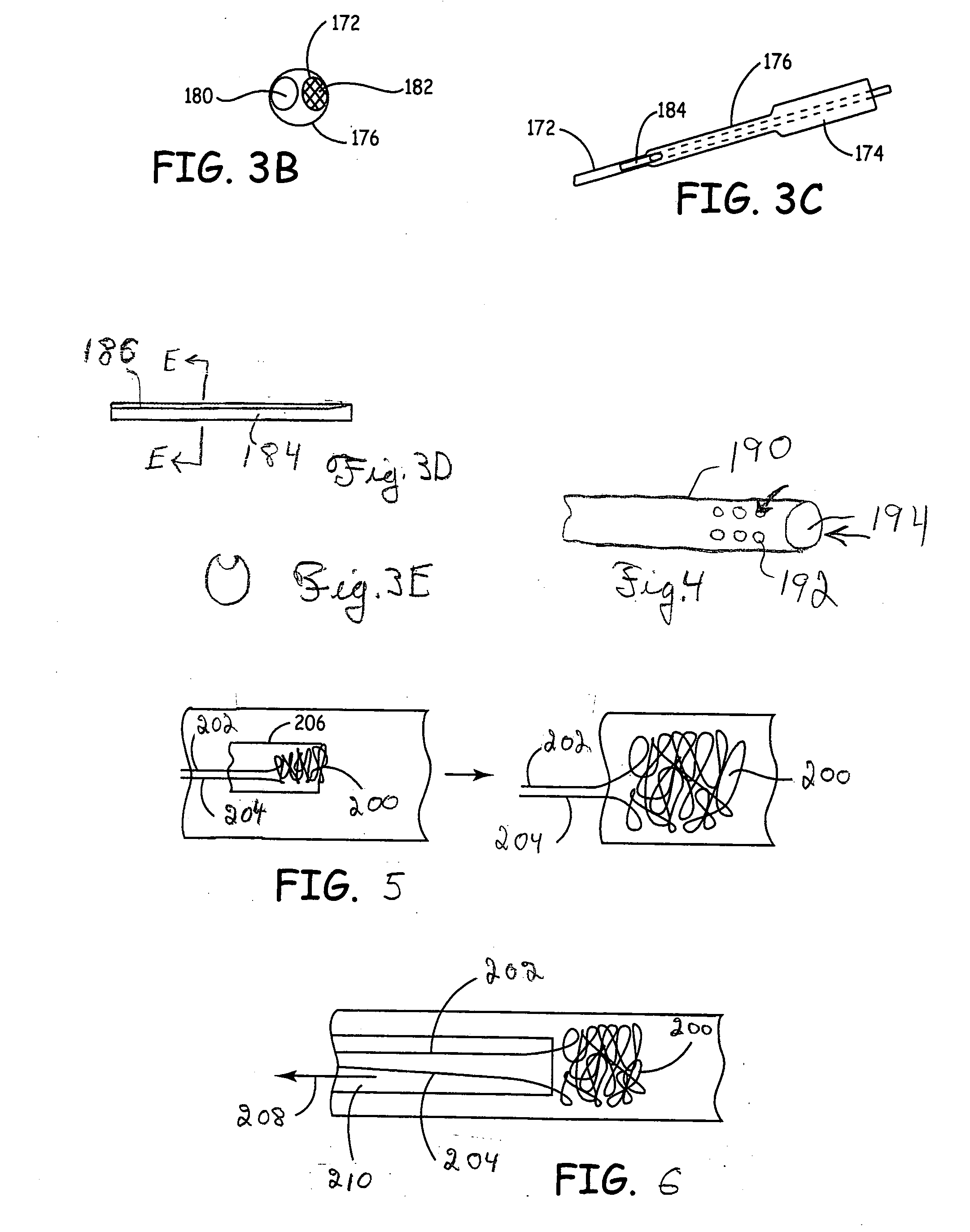
Figure 3
Abstract
Description
FIELD OF THE INVENTION
[0001] The invention relates to aspiration catheters with improved tracking. In some embodiments, the invention relates to catheters for the removal of emboli traps, i.e. embolism protection devices. For some specific embodiments, the invention relates to aspiration catheters that facilitate the removal of an embolism protection device, which can have a three-dimensional filtering matrix, from a patient's vessels with reduced or eliminated release of emboli. The invention further relates to improved method for tracking aspiration catheters. BACKGROUND OF THE INVENTION
[0002] An embolus can be any particle comprising a foreign and / or native material, which enters the vascular system or other vessel of the body with potential to cause occlusion of blood flow. Emboli can be formed from aggregates of fibrin, blood cells or fragments thereof, collagen, cholesterol, plaque, fat, calcified plaque, bubbles, arterial tissue, and / or other miscellaneous fragments or comb...
Examples
third embodiment
[0136] a deflection structure is shown in FIGS. 30-32. In this embodiment, deflection structure 510 comprises a coil 512 and a shaft 514. The coil forms a central channel 516 such that guide structure 464 traverses the central channel 516. During delivery, coil 512 extends from the tip of aspiration catheter 462, as shown in FIG. 30. Thus, coil 512 functions as a bumper. Central channel 516 also constrains the movement of the tip of aspiration catheter 462 relative to guide structure 464 such that the aspiration catheter tracks more faithfully along the guide structure. However, coil 512 does not provide a sufficient aspiration lumen. Therefore, once aspiration lumen 462 is in position or nearly so, it is desirable to remove deflection structure 510 from aspiration catheter 462.
[0137] Coil 512 can be formed, for example, from polymer or stainless steel. Metal can provide desirable levels of tensile strength. Referring to FIG. 31, deflection structure 510 can be pulled back toward th...
fourth embodiment
[0138] a deflection structure is shown in FIGS. 33 and 34. In this embodiment, deflection structure 530 comprises an elastic loop 532 and a tether534. Elastic loop 532 tends to keep its natural shape shown in FIG. 34. During deployment of aspiration catheter 462, elastic loop 534 extends from the tip of the catheter as shown in FIG. 33 and is under tension due to compression to fit within the aspiration catheter. Tension in loop 534 tends to hold deflection structure 530 in place during the delivery of aspiration catheter 462. Loop 534 can be formed, for example, from a spring metal, such as Elgiloy®, a cobalt-chromium-nickel alloy or MP35N, a nickel-cobalt-chromium-molybdenum alloy. Tether 534 can be formed from any reasonable biocompatible material.
[0139] While deflection structure 530 generally may not interfere significant with suction, deflection structure 530 can interfere with withdrawing embolism protection device 466 into aspiration catheter 462. Therefore, once aspiration ...
fifth embodiment
[0140] a deflection structure is shown in FIG. 35. In this embodiment, deflection structure 540 has a prolapsed deflection tip 542 extending from a tether 544. Prolapsed deflection tip 542 is similar to loop 532 in the embodiment in FIGS. 33 and 34. During delivery of aspiration catheter 462, the bend of prolapsed deflection tip 542 extends from the tip of the catheter to function as a bumper. Prolapsed deflection tip 542 may or may not be resilient. Prolapsed deflection tip 542 can be withdrawn partially within or fully from aspiration catheter 462 by pulling on tether 544 to remove obstruction of the catheter opening such that embolism protection device 466 can be withdrawn into the aspiration catheter. Deflection tip 542 and tether 544 may or may not be formed from the same material, such as suitable biocompatible metal(s) and / or polymer(s).