

Method and die for forming ceramics
A technology of ceramic products and molds, which is applied in the field of ceramic product forming, methods and molds, can solve the problems of simple shapes and unrealistic images of ceramic products, and achieve realistic image effects
- Summary
- Abstract
- Description
- Claims
- Application Information
AI Technical Summary
Problems solved by technology
Method used
Image

Examples
Embodiment 1
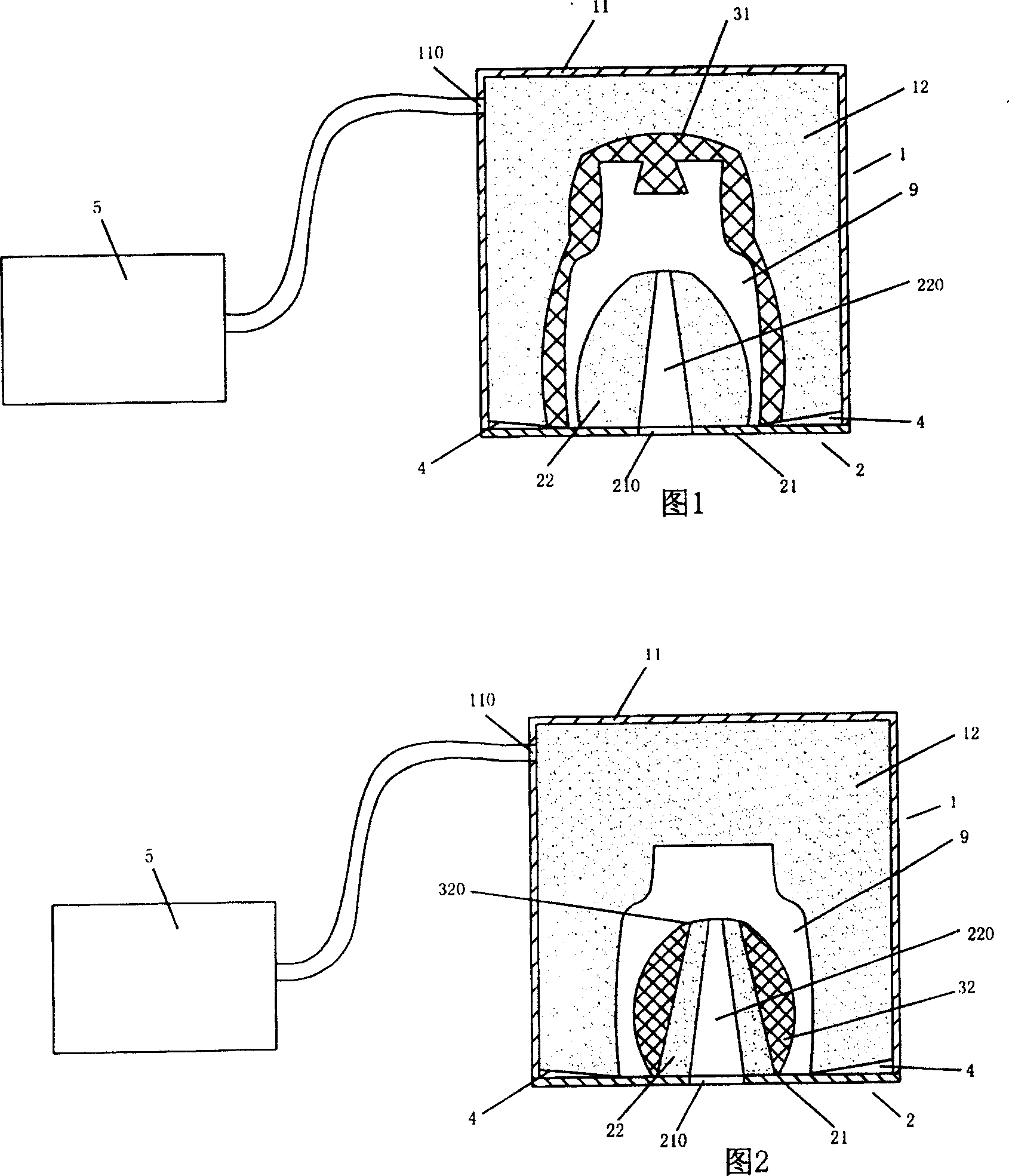
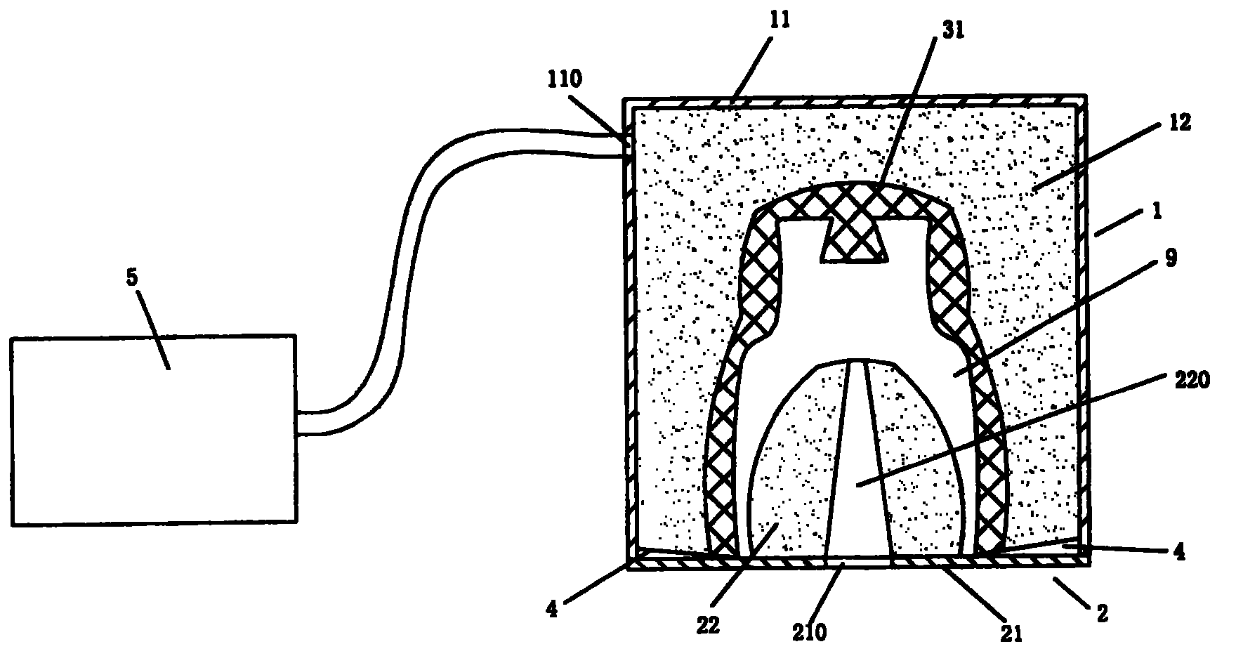
[0022] Embodiment 1, as shown in Fig. 1, a kind of mold that is used for the molding of ceramic product of the present invention comprises movable mold 1, fixed mold 2 and flexible mold cavity 31; Flexible mold cavity 31 is arranged on the cavity of upper outer mold 12, and It is fixed and fitted, the movable mold 1 and the fixed mold 2 are positioned and fitted, and the outer shell is sealed, which is convenient for vacuuming, and a cavity 9 for forming ceramic products is formed inside; the movable mold 1 includes a movable mold shell 11 and The upper outer mold 12, the movable mold housing 11 is provided with an air extraction port 110 connected with the vacuum processing device 5, and the upper outer mold 12 is arranged in the movable mold housing 11; the fixed mold 2 includes a fixed mold housing 21 and a The lower outer mold 22 of the material opening 220, the lower outer mold 220 is arranged in the fixed mold housing 21, the fixed mold housing 21 is provided with a throu...
Embodiment 2
[0024] Embodiment 2, as shown in FIG. 2 , a mold for forming ceramic products according to the present invention includes a movable mold 1, a fixed mold 2 and a flexible cavity 32, the movable mold 1 and the fixed mold 2 are positioned and fitted together, and the outer shell The body is sealed to facilitate vacuuming, and a cavity 9 for ceramic product forming is formed inside; the movable mold 1 includes a movable mold housing 11 and an upper and outer mold 12 made of porous material, and the movable mold housing 11 is provided with The suction port 110 connected by the vacuum processing device 5, the upper outer mold 12 is arranged in the movable mold housing 11; the fixed mold 2 includes a lower outer mold 22 made of a fixed mold housing 21 and a porous material, and the lower outer mold 22 is arranged In the fixed mold housing 21, the fixed mold housing 21 is provided with a through hole 210 communicating with the charging port 220 of the lower outer mold 22, and an exhaus...
Embodiment 3
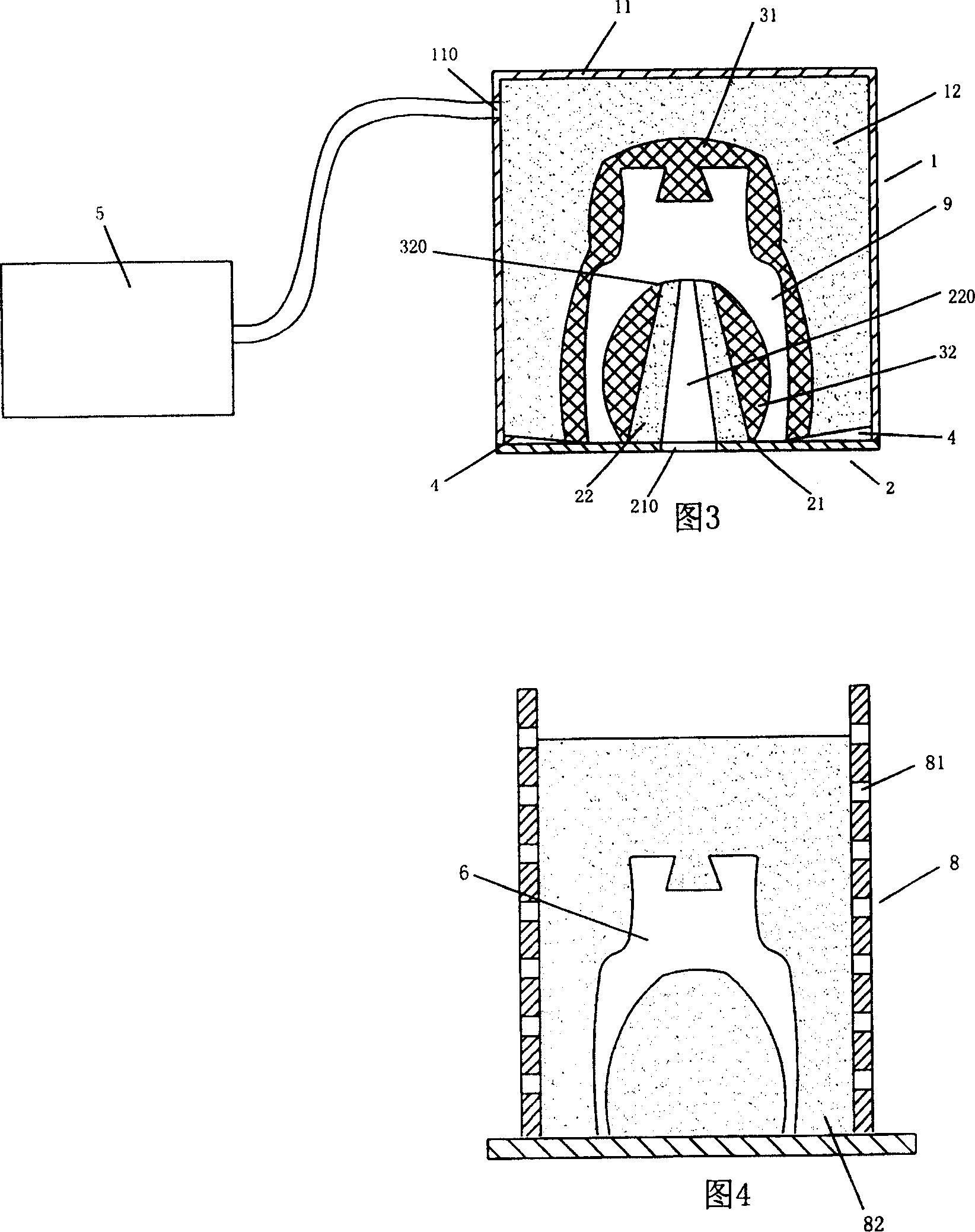
[0026] Embodiment 3, as shown in Fig. 3, another mold for forming ceramic products according to the present invention includes a movable mold 1, a fixed mold 2 and flexible cavities 31, 32, and the movable mold 1 and the fixed mold 2 are positioned and bonded together , its outer casing is sealed, which is convenient for vacuuming, and a cavity 9 for forming ceramic products is formed inside; the movable mold 1 includes a movable mold casing 11 and an upper outer mold 12 made of a porous material, and the movable mold casing 11 There is an air extraction port 110 connected to the vacuum processing device 5, and the upper outer mold 12 is arranged in the movable mold shell 11; the fixed mold 2 includes a fixed mold shell 21 and a filling port 220, which is made of a porous material. The lower outer mold 22, the lower outer mold 22 is arranged in the fixed mold housing 21, the fixed mold housing 21 is provided with the through hole 210 communicated with the charging port 220 of t...
PUM
 Abstract
Description
Claims
Application Information