Discharge lamp having cooling means

A technology for a cooling device and a lamp assembly, applied to a cooling device and a lamp assembly of a high pressure gas discharge lamp or UHP lamp), has a reflector field, and can solve problems such as affecting the optical characteristics of the lamp, problems with the cooling device, insufficient cooling, etc.

Inactive Publication Date: 2008-04-30
KONINKLIJKE PHILIPS ELECTRONICS NV
View PDF9 Cites 7 Cited by
  • Summary
  • Abstract
  • Description
  • Claims
  • Application Information

AI Technical Summary

Problems solved by technology

However, the main disadvantage of this cooling device is that the construction of the sleeve and the ducts required for the supply of compressed air adversely affect the optical properties of the lamp, since the light is screened out or the polar diagram of the light distribution is altered
[0004] In addition, when the lamp is not operating in its required operating position, the cooling device or other cooling devices may cause problems, because on the one hand any change in this position also means that the hottest area of ​​the lamp is shifted to different points and may thus be insufficiently cooled, in which case there is a risk of recrystallization of the quartz of the lamp envelope

Method used


Image

  • Discharge lamp having cooling means
  • Discharge lamp having cooling means
  • Discharge lamp having cooling means

Examples


Embodiment Construction

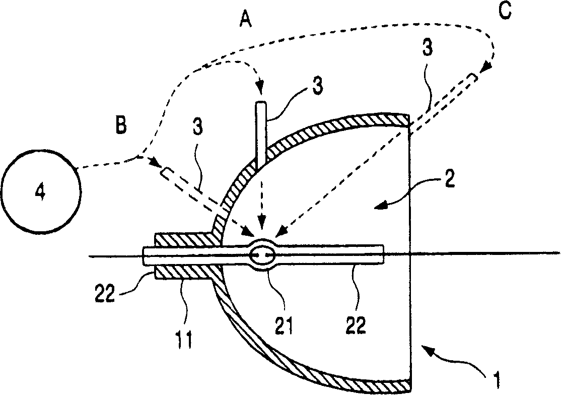
[0022] figure 1 is a schematic view of a first embodiment of the invention in the form of a reflector 1 in combination with a discharge lamp 2 and cooling means. The discharge lamp is preferably a high-pressure gas discharge lamp (HID or UHP lamp) with a discharge vessel 21 and a seal 22 between metal and quartz. The discharge lamp 2 is mounted in the diameter 11 of the reflector in the region of one of its seals 22 between metal and quartz.

[0023] The discharge vessel 21 seals the discharge chamber containing the discharge gas. When the discharge lamp is in operation, an arc discharge is excited between the ends of opposing electrodes which extend into the discharge chamber in a known manner.

[0024] The discharge lamp 2 is positioned such that the arc discharge (lighting arc) is approximately at the focal point of the reflector 1 and such that it has a beam path (light distribution polar diagram) corresponding to the shape of the reflector.

[0025] Such as figure 1 A...


PUM


Abstract

A discharge lamp, and particularly a high-pressure gas-discharge lamp (an HID (high-intensity discharge) lamp or UHP (ultra-high performance) lamp), having a reflector and a cooling means is described. The cooling means comprises at least one nozzle ( 3 ) by which a flow of gas can be directed onto the discharge lamp, the at least one nozzle ( 3 ) being so arranged that it does not extend, at least to any substantial degree, into a beam path produced by the lamp ( 2 ) and the reflector ( 1 ). In this way, the cooling means does not produce any obstacles on the beam path for the light. With preferred embodiments, it is possible to produce a turbulent flow that surrounds particularly the discharge vessel ( 21 ) of the lamp and that considerably increases the effectiveness of the cooling means. Further embodiments also allow the discharge lamp to be operated in a plurality of different positions without individual regions of the lamp being too little or too severely cooled.

Description

technical field [0001] The invention relates to a lamp assembly, in particular to a lamp assembly with a reflector, a cooling device and a high pressure gas discharge lamp (HID lamp (High Intensity Discharge Lamp) or UHP lamp (Ultra High Performance Lamp)). [0002] Discharge lamps can withstand relatively high levels of thermal stress, depending on the size of the discharge lamp, the state of installation, and its operating power. In order to avoid any shortening of the life of the discharge lamp due to thermal stress and / or further increasing its power, cooling means are used in many cases. Background technique [0003] Known, for example, from US Pat. No. 3,843,879 is a discharge lamp which is fitted by means of one of its electrode seals (extrusions) into the radial portion of the reflector. In this case, the cooling device is essentially formed by a sleeve structure connected to a source of compressed air and mounted on the other electrode seal of the lamp, through whi...

Claims


Application Information

Patent Timeline
Patent Type & Authority Patents(China)
IPC IPC(8): H01J61/52F21V29/02H01J61/86
CPCH01J61/52
Inventor J·波尔曼-雷特施H·门希W·J·梅斯E·M·E·费尔斯特雷滕
Owner KONINKLIJKE PHILIPS ELECTRONICS NV
Why Eureka
Try Eureka