
Marking machine

A scribing device and center line technology, applied to workshop equipment, manufacturing tools, etc., can solve problems such as increased weight and complex structure of scribing body

Inactive Publication Date: 2008-06-25
THK CO LTD +1
View PDF3 Cites 0 Cited by
  • Summary
  • Abstract
  • Description
  • Claims
  • Application Information

AI Technical Summary

Problems solved by technology

However, the subsequent action of the guide 7 is worsened by the moment load applied to the guide 7, and correspondingly, resistance is generated while the scribe body 2 vibrates.
[0010] In addition, the separate, i.e. independent, positions of the guide 7 for guiding the lifting movement and the guide for vibration complicate the construction of the marking body and increase its weight

Method used


Image

  • Marking machine
  • Marking machine
  • Marking machine

Examples


Embodiment Construction

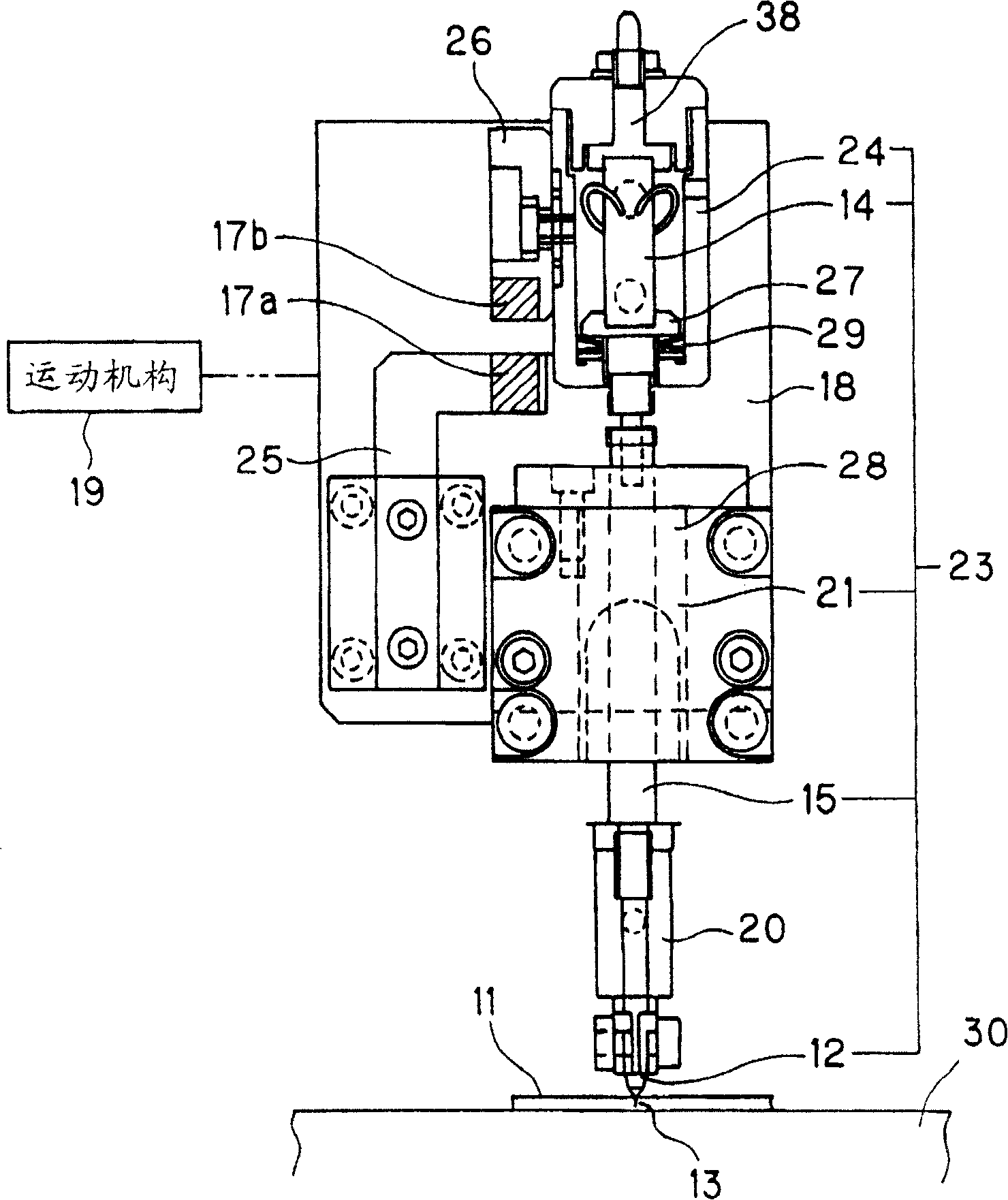
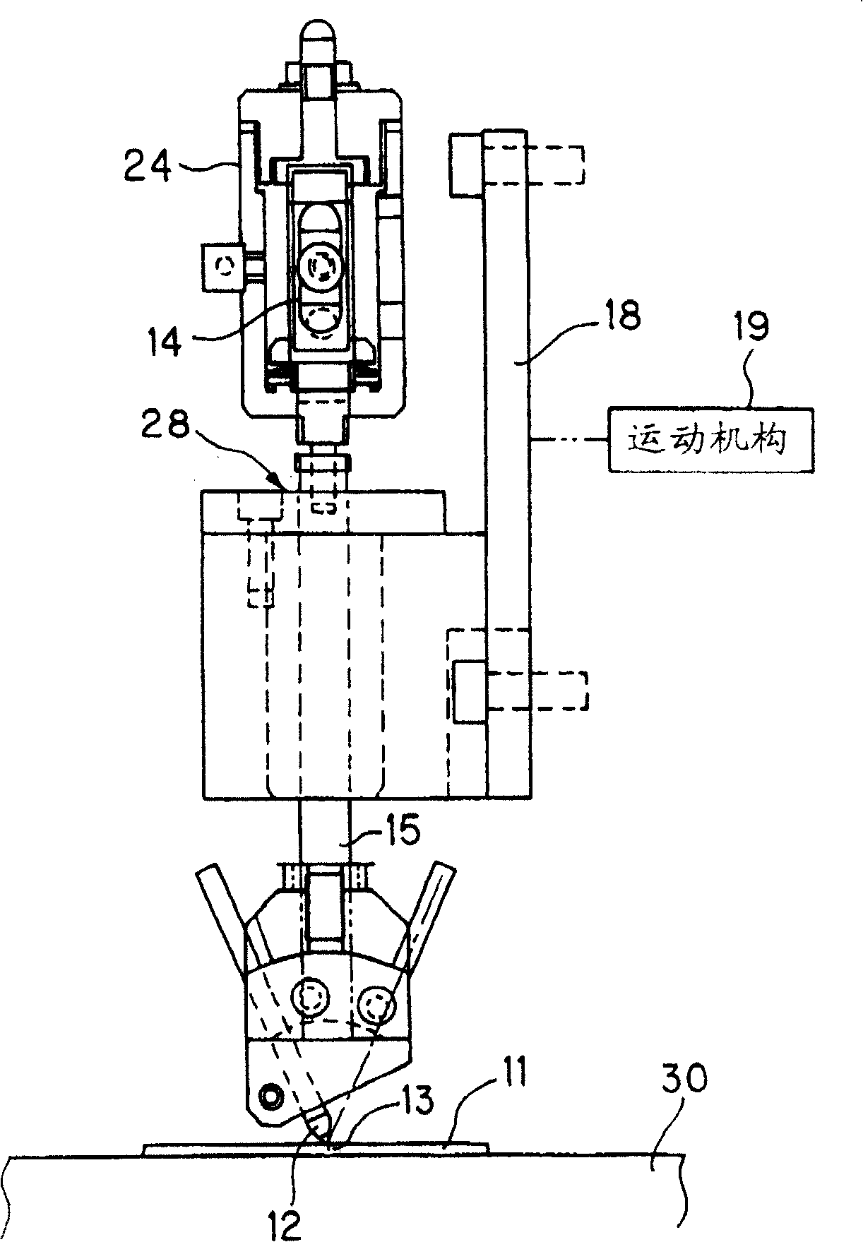
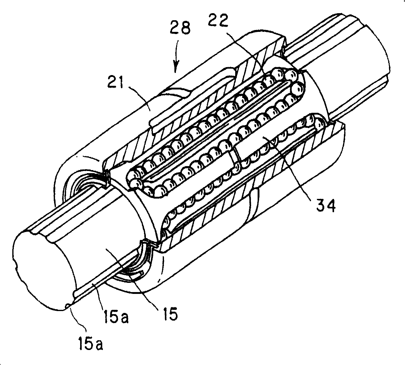
[0052] first, figure 1 and 2The scribing device shown represents the first embodiment of the present invention, and it is used for scribing on the surface of a thin plate-shaped workpiece (or workpiece) 11 made of brittle materials such as glass, semiconductor, ceramics, etc. The scribe line is drawn and thus extends along its thickness. This scribing device comprises a vibration generating part 14, a shaft 15 vertically extending from the vibration generating part 14, a cutting part 1 installed on the lower end of the shaft 15 so as to receive the vibration of the vibration generating part 14 passing through the shaft 15, a A guide 28 for guiding the linear movement of the shaft in the direction of its central axis and a pair of magnets 17a and 17b as load adjusting means utilizing magnetic force. The guide 28 is mounted on a table 18 which is movable by a motion or drive mechanism 19 which functions to move the table 18 to move the cutting member along the workpiece 11 in ...


PUM


Abstract

A marking machine for making the line marker on workpiece is composed of a vibration generator, a cutting tool for cutting on the workpiece, a vertical axle for transferring the vibration from said vibration generator to the cutting tool, a guide unit for guiding the linear movement of axle to the cutting tool in axial direction, and a load regulator for regulating the load applied to workpiece by cutting tool.

Description

technical field [0001] The present invention relates to a scribing device or a scriber for forming (scribing) a scribed line on a workpiece made of brittle material such as glass, semiconductor or the like. Background technique [0002] There are known scribing devices for forming a scribed line on the surface of a workpiece or workpiece. In operation, when a vibrating cutting piece is pressed against the surface of the workpiece, a vertical crack will be created on the surface of the workpiece and thereby extend through the thickness of the workpiece, in this case when the cutting piece is on the surface of the workpiece When moving, a continuous line (crack) will be generated on the surface of the workpiece. After such a scribed (scribed) line, the workpiece is broken by bending the workpiece along the scribed line. [0003] FIG. 7 shows a scribing device of conventional construction and provided with a scribing body 2 for vibrating the cutting element 1 . The scribe bo...

Claims


Application Information

Patent Timeline
Patent Type & Authority Patents(China)
IPC IPC(8): B25H7/04
Inventor 石川裕一
Owner THK CO LTD
Learn More