
Rock bit

a technology of rock bit and rock casing, which is applied in the direction of drilling rods, drilling pipes, drilling casings, etc., can solve the problems of critical accident, wear-out of seals, and insufficient robustness of the bit body, so as to reduce the burden on the bearing portion 8 and reduce horizontal vibration. , the effect of reducing the cutting of mud

Inactive Publication Date: 2011-07-28
TIX HLDG COMPANY
View PDF17 Cites 0 Cited by
  • Summary
  • Abstract
  • Description
  • Claims
  • Application Information

AI Technical Summary

Benefits of technology

[0022]The first of the present invention provides a tip 20 of a gauge surface 16 with a grinding capability to allow the tip 20 to actively dig the well wall, thus releasing stress applied to the rock bit. Hence, burdens on the bearing portion 8 are reduced. The first of the present invention further allows horizontal vibration to be suppressed, thus reducing cutting of mud into the seal 10. Manufacturing the bit such that the burdens on the journal portion 2 and the seal 10 are reduced is an innovative new attempt.
[0023]When the diamond composite material is extensively disposed on the gauge surface 16 so as to eliminate protruding portions, the possible horizontal vibration of the cone portion 6 during rotation can be prevented.
[0024]As a result, cutting of sediment into the seal 10 is reduced, thus enhancing the seal 10.
[0026]The outer peripheral portion of the bit rotates at high speed, and this meets a grinding condition for the ring bit. However, the central portion of the bit rotates at low speed. Thus, it is ideal to use a tri-cone bit to crush rocks during digging according to the conventional example. Furthermore, the cylindrical ring portion 30 prevents digging debris from entering the seal 10 and increases cooling efficiency to protect the seal from high temperature such as geothermal heat. In this case, the tri-cone bit need not serve to maintain the digging diameter (the ring bit instead fulfils this function), and there is no need to worry about the wear of the gauge surface or the like.

Problems solved by technology

These are measures for enhancing the wear resistance of the gauge surface and are not designed to suppress stress and vibration.
Moreover, a critical accident may occur; the cone portion 6 may slip off from the journal portion 2.
However, the bit body 4 is not so robust as it appears.
This results in wear-out of the seal 10, entry of sediment into the bearing portion 8, and wear-out of the bearings caused by the sediment acting as an abrasive material.

Method used


Image

  • Rock bit
  • Rock bit
  • Rock bit

Examples


embodiment 1

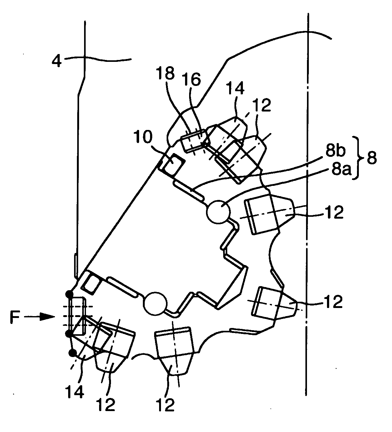
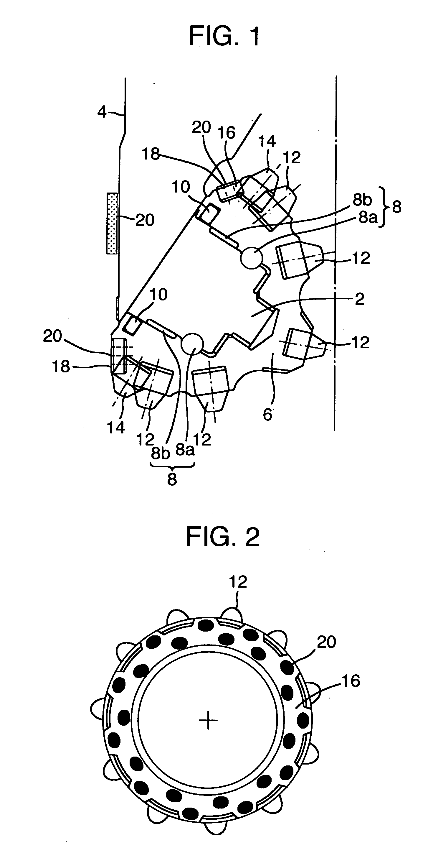
[0039]An embodiment of a rock bit according to the present invention will be described with reference to FIG. 1. The rock bit includes a bit body 4 with a journal portion 2, a cone portion 6 configured to be rotatable with respect to the bit body 4, and a bearing portion 8 located between the cone portion 6 and the journal portion 2. The bearing portion 8 includes a ball bearing 8a and a metal bearing 8b. The rock bit further includes a seal 10 provided between the cone portion 6 and the journal portion 2 to seal the bearing portion 8. A large number of cemented carbide tips 12 and 14 are embedded in the cone portion 6. The cemented carbide tips include cemented carbide tips 12 that contact the bottom of a well and gauge tips 14 that contact the side wall of the well.

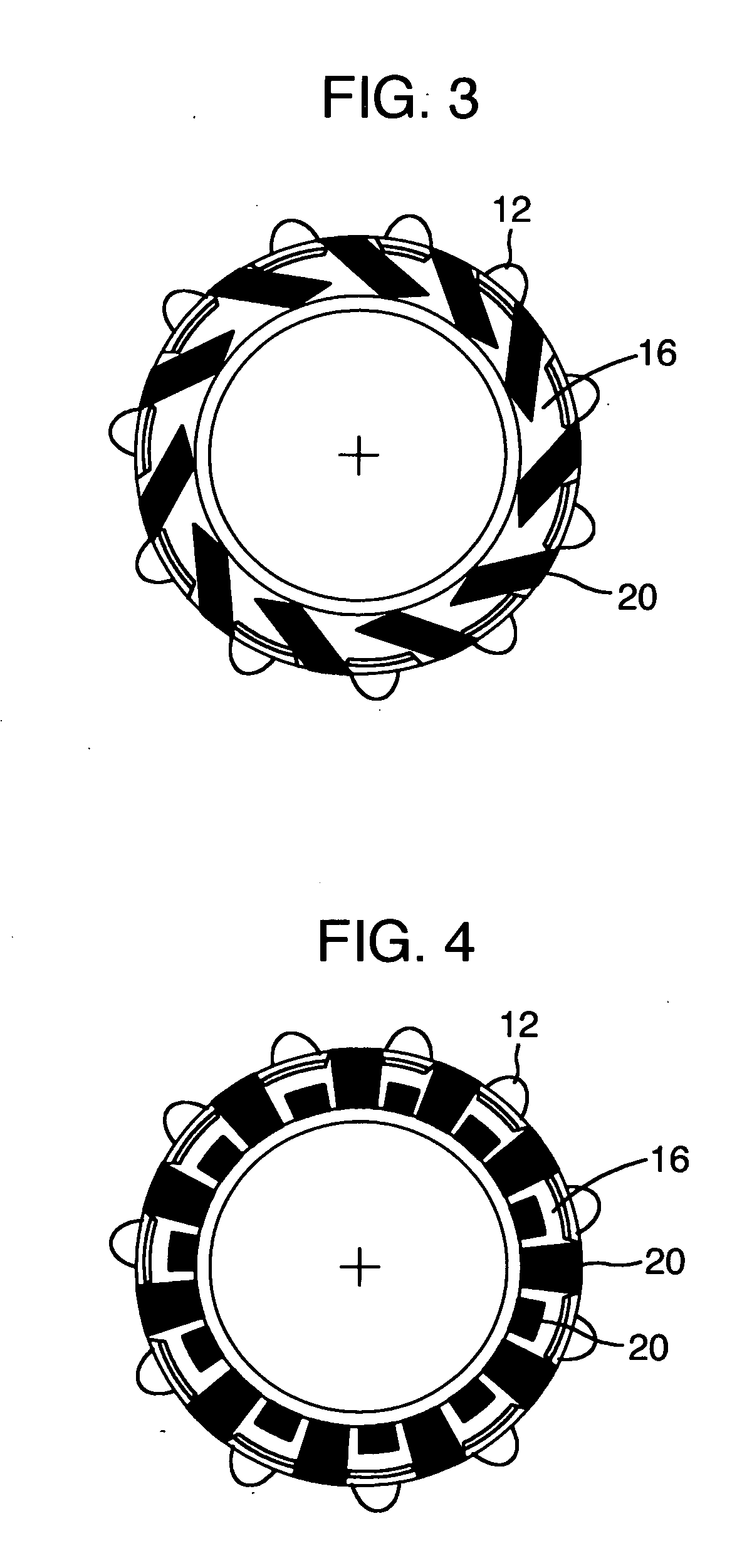
[0040]The cone portion 6 includes a gauge surface 16 that contacts the side wall of the well. Cemented carbide gauge surface tips 18 are provided on the gauge surface 16. A diamond composite material 20 is disposed on t...

embodiment 2

[0054]Now, a rock bit according to another embodiment of the present invention will be described with reference to FIG. 9. Like the rock bit according to Embodiment 1, this tri-cone bit includes a bit body 4 with a journal portion 2, a cone portion 6 configured to be rotatable with respect to the bit body 4, and a bearing portion 8 located between the cone portion 6 and the journal portion 2. The bearing portion 8 includes a ball bearing 8a and a metal bearing 8b. The rock bit further includes a seal 10 provided between the cone portion 6 and the journal portion 2 to seal the bearing portion 8.

[0055]Unlike in the case of Embodiment 1, a ring portion 30 is provided at the outer peripheral portion of the bit body 4. A ring bit 32 is provided at the tip of the ring portion 30. Furthermore, the cone portion 6 of the tri-cone bit includes no gauge tip or gauge surface tip which contacts the side wall of the well but only cemented carbide tips 12 that contact the bottom of the well.

[0056]...


PUM


Abstract

The present invention provides a rock bit which enables a reduction in surface pressure from a well wall and which allows possible vibration to be suppressed. A first of the present invention provides a rock bit including a bit body with a journal portion, a cone portion configured to be rotatable with respect to the bit body, a bearing portion located between the cone portion and the journal portion, and a seal provided between the cone portion and the journal portion to seal the bearing portion, wherein the cone portion includes a gauge surface that contacts a side wall of a well, and a diamond composite material is preferably disposed extensively and smoothly on the gauge surface. In a second aspect of the present invention, a ring bit is provided at an outer peripheral portion of a bit body. Furthermore, a cone portion of a tri-cone bit includes no gauge tip or surface chip that contacts the side wall of the well but only cemented carbide tips that contact a bottom of the well.

Description

INCORPORATION BY REFERENCE[0001]The present application claims priority from Japanese application JP2010-013040 filed on Jan. 25, 2010, the content of which is hereby incorporated by reference into this application.BACKGROUND OF THE INVENTION[0002](1) Field of the Invention[0003]The present invention relates to a rock bit.[0004](2) Description of Related Art[0005]Tri-cone bits have recently been used as rock bits for well digging.[0006]As shown in FIG. 10, a tri-cone bit includes a bit body 4 with a journal portion 2, a cone portion 6 configured to be rotatable with respect to the bit body 4, a bearing portion 8 located between the cone portion 6 and the journal portion 2, and a seal 10 provided between the cone portion 6 and the journal portion 2 to seal the bearing portion 8. A large number of cemented carbide tips 12 and 14 are embedded in the cone portion 6. The cemented carbide tips include cemented carbide tips 12 that contact the bottom of a well and gauge tips 14 that contac...

Claims


Application Information

Patent Timeline
Patent Type & Authority Applications(United States)
IPC IPC(8): E21B10/46
CPCE21B10/26E21B17/1092E21B10/28
Inventor KURIBAYASHI, NOBUHIRO
Owner TIX HLDG COMPANY
Learn More