Sawing machine and method for controlling a sawing machine

A technology of sawing machines and saw blades, which is applied in the field of bow sawing machines to achieve the effect of prolonging life and avoiding damage

Active Publication Date: 2014-12-24
KEURO BESITZ & EDV DIENSTLEISTUNGS
View PDF12 Cites 7 Cited by
  • Summary
  • Abstract
  • Description
  • Claims
  • Application Information

AI Technical Summary

Problems solved by technology

This avoids damage to the saw blade due to excessively high feed rates, but this requires additional sensor measures

Method used


Image

  • Sawing machine and method for controlling a sawing machine
  • Sawing machine and method for controlling a sawing machine
  • Sawing machine and method for controlling a sawing machine

Examples


Embodiment Construction

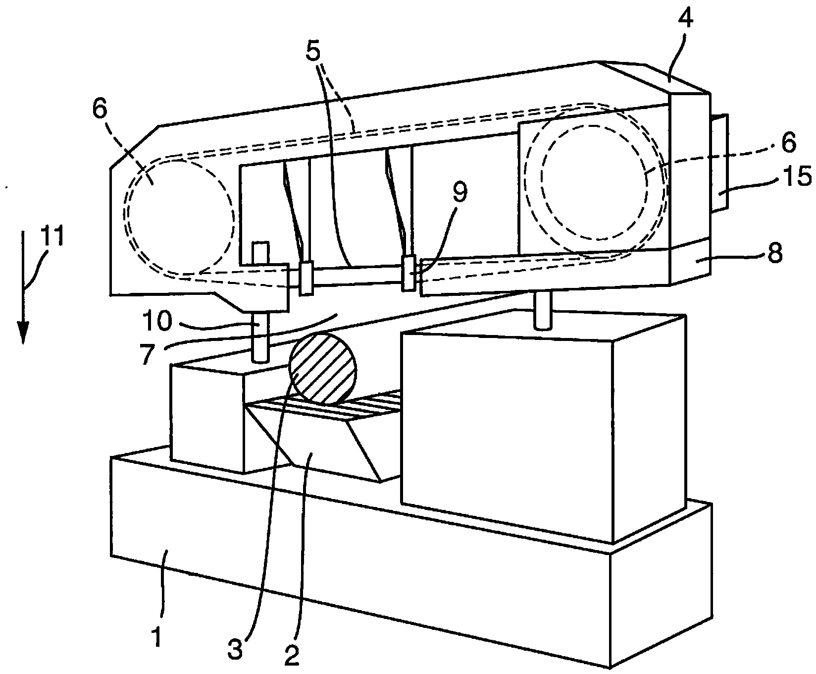
[0039] figure 1 Schematically shows a band sawing machine with: a base 1; a saw table 2 mounted on the base 1 for a workpiece 3 to be sawed; and a saw module 4 movable relative to the base 1, in which the The saw band 5 runs around the two rollers 6 without interruption. In the cutting area 7 , the saw band 5 runs outside the saw module housing 8 , where the saw band is guided by two saw band guides 9 arranged on the right and left of the cutting area 7 . These saw band guides 9 each comprise two lateral saw band guides and a saw band back guide, wherein the saw band back guide is damped by means of a spring set, so that the saw band 5 can be elastic against the force of the spring set retreat upwards.

[0040] The saw module 4 is located on the guide part 10 and can move up and down relative to the base 1 . The lowering movement is the sawing feed movement 11 .

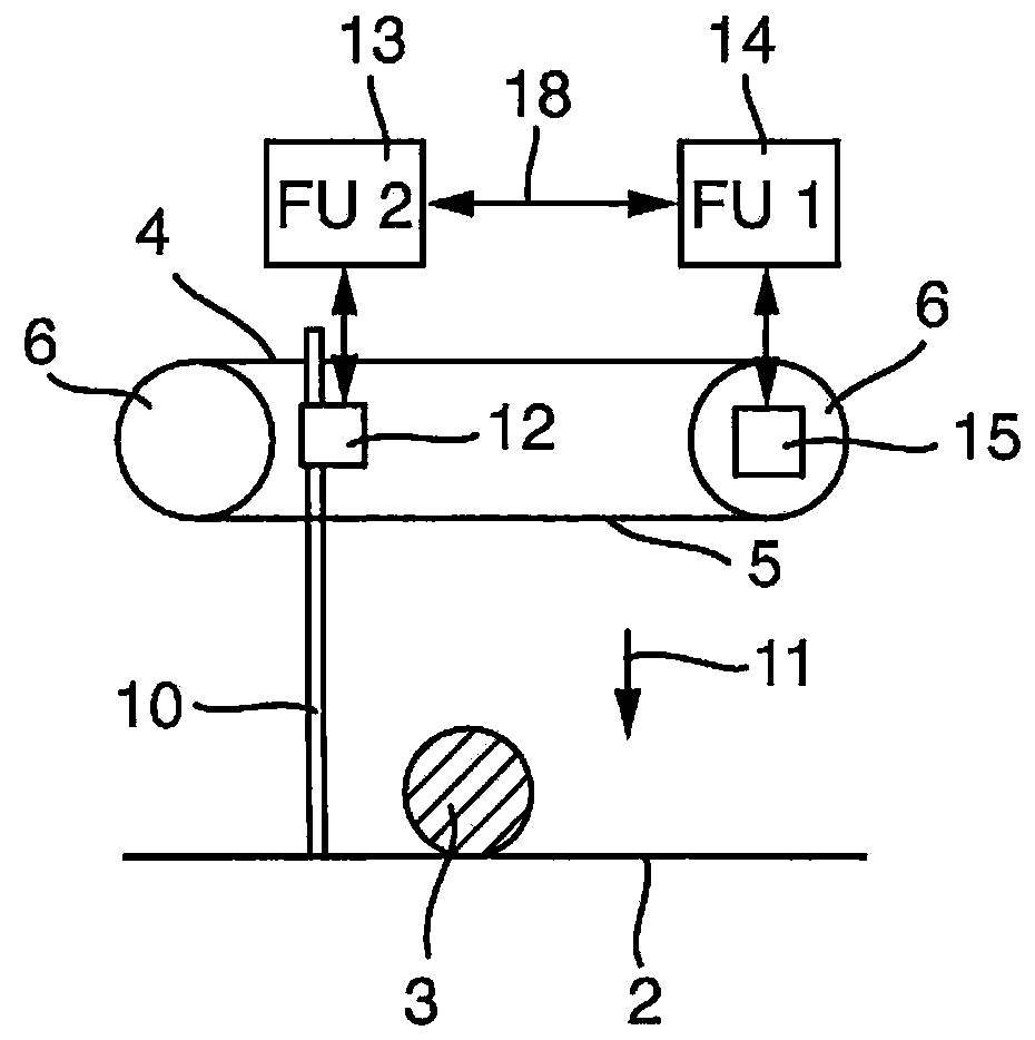
[0041] combine figure 2 (as figure 1 A schematic diagram of the basic components of the invention of the ba...


PUM


Abstract

A method for controlling a sawing machine with a sawing tool, which is driven by an electrical sawing tool drive with a first frequency converter, and with a sawing feed device for moving the driven sawing tool at a feed rate in relation to a workpiece to be sawn, and also to such a sawing machine. The feed rate is changed over from an idling feed rate to a working feed rate when the sawing tool engages in the workpiece. A value of a physical variable which corresponds to the torque transferred from the sawing tool drive to the sawing tool or from which a change in this torque can be calculated is determined here at the first frequency converter. The changeover from the idling feed rate to the working feed rate takes place in dependence on the value of this physical variable.

Description

technical field [0001] The invention relates to a method for controlling a sawing machine according to the preamble of claim 1 and a sawing machine according to the preamble of claim 12 . Such a sawing machine includes a saw blade which is driven by a chainsaw blade drive with a first frequency converter. A saw feed device is also provided for moving the driven saw blade relative to the workpiece to be sawed at a feed speed. The sawing feed device is constructed such that the feed speed for driving the saw blade is switched from an idle feed speed to a working feed speed when the saw blade acts on the workpiece. [0002] Sawing machines of the aforementioned type are usually designed as band saws or circular saws. The invention also includes other types of sawing machines, especially bow sawing machines. [0003] The main field of application of the invention concerns sawing machines of the aforementioned type for cutting or sawing metal workpieces. Background technique ...

Claims


Application Information

Patent Timeline
IPC IPC(8): B23Q17/00B23D59/00
CPCB23D53/04B23D55/088B23D59/001Y10T83/4463Y10T83/04B23Q17/20B23Q15/013B23D36/0041B23D55/06B23Q5/28B23Q5/10B23Q5/00Y10T83/7076Y10T83/141
Inventor 马库斯·奥伯尔安德烈·塞贝尔
Owner KEURO BESITZ & EDV DIENSTLEISTUNGS
Why Eureka
Try Eureka