Orthopedic fastener device

a technology of orthopedic fasteners and proximal ends, which is applied in the direction of fasteners, internal osteosynthesis, osteosynthesis devices, etc., can solve the problems of inability to accurately orient the fastener, difficulty in registering the fastener at the distal end with another instrumentality, and several common frailties of surgical procedures involving fasteners on skeletal structures. , to achieve the effect of minimal damage to bone and greater retention of bone structur

Active Publication Date: 2018-02-27
RTG SCI LLC
View PDF21 Cites 8 Cited by
  • Summary
  • Abstract
  • Description
  • Claims
  • Application Information

AI Technical Summary

Benefits of technology

[0016]The instant invention addresses various skeletal components with fasteners in ways heretofore unattainable with an improved thread pattern which provides greater retention of bone structure and minimal damage to bone adjacent the fastener.
[0017]This invention produces a bone screw thread design that can be modified in many independent ways to produce different capabilities and functions that can contribute to better grip, greater resistance to pull-out, lower cutting and insertion pressure which reduces site temperature and causes less damage to the bone in the process. These features provide better feel for the surgeon installing the screws to prevent stripped threads, better clamping force, better fixation, and ultimately shorter healing time.
[0018]A new manufacturing process is disclosed which utilizes single-point threading in conjunction with multiple form cutting tools with different shapes and following different paths to create thread features formed by independently programmable successive cutting moves, each distinct from the others. This means that the tooth height, thickness and spacing can now each be modified independently to produce different characteristics and capabilities to greatly improve both the procedure when the screw is installed into the bone and the performance of the screw in situ.

Problems solved by technology

Surgical procedures involving fasteners on skeletal structure presently suffer from several common frailties.
One is the inability to accurately orient the fastener during insertion to keep the fastener from wandering.
Even with a predrilled pilot hole, fasteners still frequently skew off the axis of the pilot hole, making it difficult to register the fastener at its distal end with another instrumentality.
Another frailty is the failure to provide a reliable thread portion that engages the bone of the patient in a manner which retards its working loose.
Unfortunately, buttress threads are suitable for use only where load forces on the fastener are applied in one direction.
Where the load forces are multidirectional or not unidirectional and axial, failure can occur.
One manifestation of buttress thread failure is “toggling” where the fastener works on the bone and enlarges the hole within which the fastener resides.
Yet another frailty related to high insert torque makes it impossible to insert the screw through bone fragments without it grabbing the fragment and causing it to rotate with the screw causing significant trauma to soft tissues and a failed fixation of the fragment.
Increased friction leads to elevated temperatures during insertion, potentially damaging bone tissue.
A temperature excursion greater than 116 degrees Fahrenheit (47 degrees Celsius) at the insertion site causes osteonecrosis which cannot be repaired and which the body cannot heal.
And, even worse, excess heat compromises the fastener's ability to remain in place since the bone has died at the screw thread interface.
As a consequence, some procedures rely on liquid cooling at the site during the drilling / insertion procedure, but, even then, the process generates so much heat that the heat generating tool can be too hot to touch because the liquid cooling is merely topical.
Since the only variables (thread pitch, crest and root diameters) in the buttress thread design are interrelated, improving retention increases friction and insertion torque, resulting in heat generation and impairing the surgeon's ability to feel the insertion torque of the fastener in a meaningful way.
This still leaves the fundamental problem of the thread's inability to withstand multidirectional forces unaddressed, while creating several new problems.
The buttress fastener is harder to start and is prone to stripping, especially when used in conjunction with a plate.
The buttress thread induces a radial force, perpendicular to the fastener's long axis, which increases the probability the bone will split or crack, making a procedure much more difficult, if not impossible.
The buttress threaded fastener can wander during insertion, making its registry with an instrumentality at the distal end of the fastener a recurring problem.
Wandering away from the pilot hole often results in cutting new threads in an unintended location or stripping out the pilot hole which retards healing and actually induces trauma; and, where there is a temperature excursion above 116 degrees Fahrenheit, it can also cause osteonecrosis of the adjacent bone.
This bone debris accumulates along the thread teeth and increases insertion torque and friction which therefore generate additional heat.
The debris also makes the fastener harder to insert and provides a poor interface with the bone and the fastener.
Another problem associated with buttress style threads is that the area between threads of the fastener is the only site of anchoring in the bone, and because of the design constraints associated therewith, this site is difficult to optimize.
Stated alternatively, the metal of the fastener is orders of magnitude stronger than the retaining bone so that when failure occurs, it always involves bone trauma.

Method used


Image

  • Orthopedic fastener device
  • Orthopedic fastener device
  • Orthopedic fastener device

Examples


Embodiment Construction

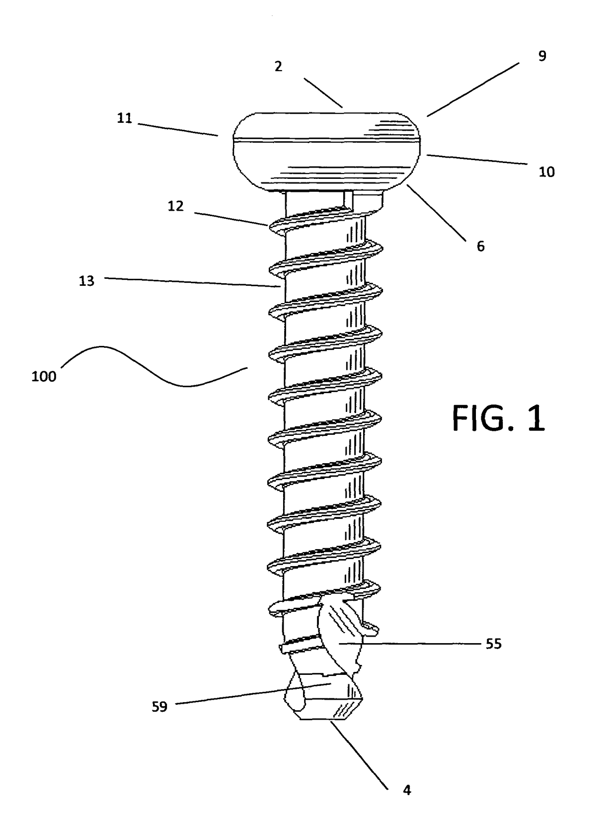
[0050]Considering the drawings, wherein like reference numerals denote like parts throughout the various drawing figures, reference numeral 100 is directed to the orthopedic stabilization fastener according to the present invention.

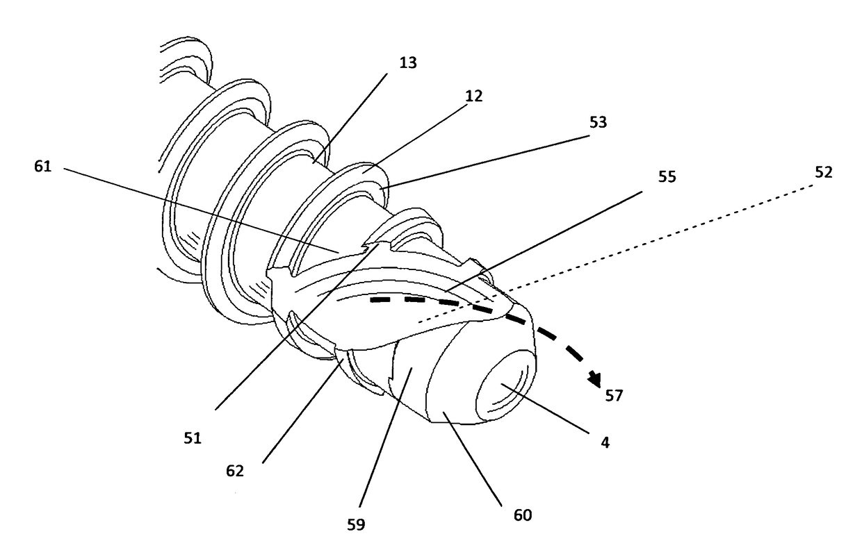
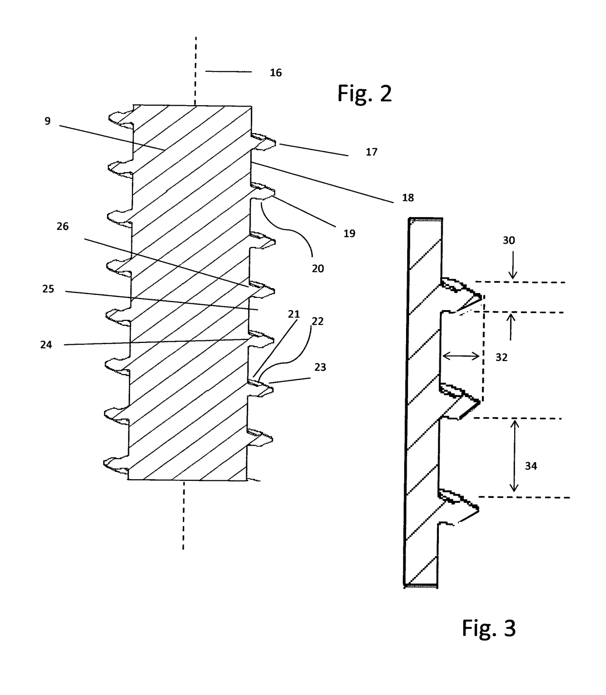
[0051]The features of the screw threads in FIG. 1 include: the head 2 (defining a proximal end) of the screw is comprised of radii 9 and 10 converging at apex 11 to form the outside diameter of the head 2. The head 2 may include a lower wall 6 which defines an abutment surface so that, when the fastener 100 is fully installed, the abutment surface 6 bears against a supporting surface (e.g. patient's body or plate) and induces the compressive load 5 shown in FIG. 11. As load 5 in induced, centering points 36FIG. 11 of screw teeth 24 are loaded against the bottom centering points 37 of bone teeth 25 which prevents radial inward or outward forces 3 from axis 16 of the screw. Likewise, load vector 1FIG. 11 induces screw centering point 38 against bone centeri...


PUM


Abstract

An orthopedic structure includes a method for making a threaded fastener with thread geometry and leading edge geometry which provides greater precision during installation. Specifically, thread pitch and tooth profiles are independently variable. A leading portion of the fastener advances bone shards forward of the forward of the fastener to reduce insertion torque and prevent the shards from residing in the upstream tooth profile for better retention.

Description

FIELD OF THE INVENTION[0001]The instant invention is directed generally to devices used by surgeons primarily to embed in bone and to repair fractures. More specifically, the instant invention includes a fastener capable of rotation about an axis that is fashioned to, inter alia, resist working loose and reduce insertion torque, thereby providing both tactile feedback to the surgeon and minimize trauma at the fastening site by controlling heat buildup due to friction. The fastener reduces insertion (cutting) pressure and increases fastener tracking, thereby minimizing problems associated with misalignment.BACKGROUND OF THE INVENTION[0002]Surgical procedures involving fasteners on skeletal structure presently suffer from several common frailties. One is the inability to accurately orient the fastener during insertion to keep the fastener from wandering. Bone interiors have a sponge like (cancellous) texture. Even with a predrilled pilot hole, fasteners still frequently skew off the a...

Claims


Application Information

Patent Timeline
Patent Type & Authority Patents(United States)
IPC IPC(8): A61B17/86
CPCA61B17/8625A61B17/8635A61B17/866A61B17/863
Inventor REED, GARY JACK
Owner RTG SCI LLC
Why Eureka
Try Eureka