

Industrial automatic slitting device for batch potato powder
An automatic, potato flour technology, applied in metal processing and other directions, can solve the problems of time-consuming, labor-intensive, inconvenient operation, manpower and other problems, and achieve the effect of easy use and cutting saving.
- Summary
- Abstract
- Description
- Claims
- Application Information
AI Technical Summary
Problems solved by technology
Method used
Image

Examples
specific Embodiment approach 1
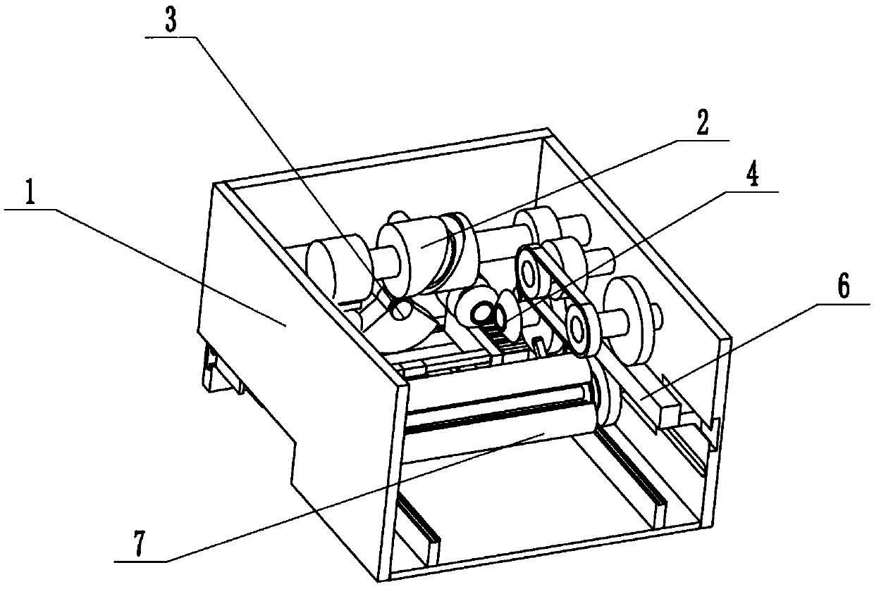
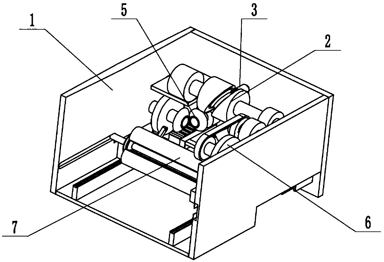
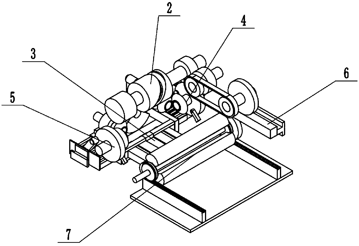
[0031] Such as Figure 1 to Figure 12 As shown, an industrialized automatic cutting device for potato flour in batches, including a bracket support 1, a driver 2, an intermittent propulsion cutter 3, a right push clamp 4, a left push clamp 5, and a clamp propeller 6 and the clamper 7, the driver 2 is fixedly connected to the support support 1, the upper end of the intermittent propulsion cutter 3 is slidably connected in the driver 2, and the lower end of the intermittent propulsion cutter 3 is slidably connected to the back of the inner wall of the support support 1 end, the right pusher 4 and the left pusher 5 are respectively slidably connected to the left and right ends of the inner wall of the bracket support 1, the clamping propeller 6 is engaged with the driver 2 for transmission, and the upper end of the clamper 7 is in contact with the clamping propulsion The gear 6 is engaged with the transmission, and the clamp 7 is slidably connected in the bracket support 1. Place ...
specific Embodiment approach 2
[0032] Such as Figure 1 to Figure 12 As shown, this embodiment will further explain Embodiment 1. The bracket support 1 includes a fixed stop frame 1-1, an extruded bottom plate 1-2, a front rack T-shaped chute 1-3, and two position-limiting T-shaped chute 1-4, right rack chute 1-5, two rotating shaft chute 1-6 and two pulley slides 1-7, extruded bottom plate 1-2 is fixedly connected to fixed stop frame 1-1 On the rear side of the lower end, two pulley slides 1-7 are respectively fixedly connected to the left and right sides of the upper end of the extruded bottom plate 1-2, and the front rack T-shaped chute 1-3 is arranged behind the inner wall of the fixed stop frame 1-1 On the lower side of the end, two limit T-shaped chutes 1-4 are respectively arranged on the left and right ends of the inner wall of the fixed stop frame 1-1, and the right rack chute 1-5 is arranged on the right end of the inner wall of the fixed stop frame 1-1. The two rotating shaft slide grooves 1-6 a...
specific Embodiment approach 3
[0033] Such as Figure 1 to Figure 12 As shown, this embodiment will further illustrate the second embodiment, the driver 2 includes a servo motor 2-1, a main shaft 2-2, a drive block 2-3, an elliptical drive groove 2-4 and a drive main gear 2-5 , the servo motor 2-1 is fixedly connected to the inner wall of the fixed frame 1-1, the left end of the main shaft 2-2 is connected to the drive shaft of the servo motor 2-1 through a coupling, and the right end of the main shaft 2-2 is connected to the servo motor in rotation The right end of the inner wall of 2-1, the driving block 2-3 is fixedly connected to the middle end of the main shaft 2-2, the elliptical driving groove 2-4 is arranged on the driving block 2-3, and the driving main gear 2-5 is fixedly connected to the main shaft 2 The right side of -2. Servo motor 2-1, main shaft 2-2, drive block 2-3, ellipse drive groove 2-4 and drive main gear 2-5 make the power source of device.
PUM
 Abstract
Description
Claims
Application Information