Supercharge Your Innovation With Domain-Expert AI Agents!

Front image taking device

一种摄影装置、摄像机的技术,应用在放映装置、洗印装置、测量装置等方向,能够解决不能判断边缘、行人移动速度移动速度慢、分界线不清楚等问题

Inactive Publication Date: 2009-03-25
OMRON CORP
View PDF4 Cites 4 Cited by
  • Summary
  • Abstract
  • Description
  • Claims
  • Application Information

AI Technical Summary

Problems solved by technology

However, the moving speed of the pedestrian is extremely slow compared with the moving speed of the own vehicle. Therefore, when the speed of the own vehicle is fast, the relative movement of the pedestrian is relatively large. Therefore, as shown in FIG. 6(C), the pedestrian is obviously not moving according to the Within the area set in Figure 6(A)
In this case, the optimum aperture value cannot be set
In the device of Patent Document 1, the previous aperture control area is directly used when the preceding vehicle cannot be recognized, so the preceding vehicle is missed
[0011] (3) When photographing a leading car that is dirty with mud, etc., the boundary line between the glass and the body of the car is not clear, or the boundary line between the taillight and the body is not clear
For the photographic image of this car, even if the image processing of edge detection is performed, the boundary cannot be judged because the dividing line is unclear.
Although the aperture control is proposed in the device of Patent Document 1, the aperture control can only adjust the brightness and cannot adjust the contrast
Therefore, in the device of Patent Document 1, edge detection cannot be efficiently performed on objects with unclear boundaries such as dirty cars.

Method used


Image

  • Front image taking device
  • Front image taking device
  • Front image taking device

Examples


Embodiment Construction

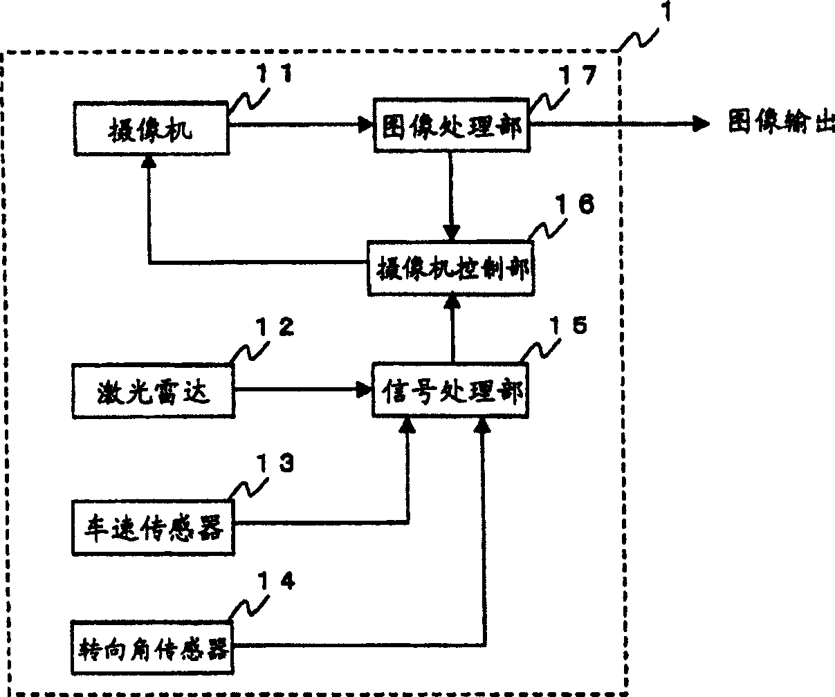
[0032] Hereinafter, a forward imaging device according to an embodiment of the present invention will be described with reference to the drawings. figure 1 It is a block diagram of the front imaging device 1 . As shown in the figure, the front imaging device 1 includes a camera 11 , a laser radar 12 , a vehicle speed sensor 13 , a steering angle sensor 14 , a signal processing unit 15 , a camera control unit 16 , and an image processing unit 17 . The camera 11 is connected to a camera control unit 16 and an image processing unit 17 . The laser radar 12 , the vehicle speed sensor 13 , and the steering angle sensor 14 are connected to a signal processing unit 15 . In addition, the signal processing unit 15 is connected to the camera control unit 16 , and the camera control unit 16 is connected to the image processing unit 17 .

[0033] The camera 11 is installed in front of the vehicle, for example, on the inner side of the windshield (inner side of the rearview mirror). The ...


PUM


Abstract

A front image taking device uses a laser scan device to scan an area in front of an automobile to detect an obstacle and a vector representing its displacement over a period of one frame of the scan is obtained by a signal processor. A camera controller predicts from this vector the position of the obstacle at the time of the next frame and sets an image-taking area. A camera obtains a preliminary image of the area and its brightness histogram is obtained by an image processor. The camera controller adjusts the camera according to the histogram such that an image of the area with optimum brightness and contrast is obtained.

Description

technical field [0001] The present invention relates to a front photographing device for photographing the front of a car, and more particularly to a front photographing device for setting photographing conditions according to the state of a subject. Background technique [0002] Conventionally, in order to ensure the safety of automobiles, lidar is used to detect the distance to the preceding vehicle. The laser radar is used to detect the distance to the preceding vehicle, and when the vehicle is abnormally close to the preceding vehicle, an alarm is issued to remind the driver to pay attention. [0003] Furthermore, in order to further ensure safety, it is preferable to detect not only the distance to the preceding vehicle but also the distance to other objects such as pedestrians. Although LiDAR can detect the distance and direction to an object in a short time, it is difficult to judge whether the object is a car or a pedestrian. [0004] In order to determine the type...

Claims


Application Information

Patent Timeline
Patent Type & Authority Patents(China)
IPC IPC(8): G03B29/00G01S17/93G01S17/08G01S17/86G01S17/931
CPCG06K2209/23G01S17/936G06K9/00805G08G1/16G06K9/4647G06K9/00791G01S17/42G06K9/00369G01S17/023G08G1/166G03B7/003G01S17/86G01S17/931G06V40/103G06V20/58G06V10/507G06V2201/08
Inventor 堀部刚治
Owner OMRON CORP
Features
  • R&D
  • Intellectual Property
  • Life Sciences
  • Materials
  • Tech Scout
  • Unparalleled Data Quality
  • Higher Quality Content
  • 60% Fewer Hallucinations
Learn More