Fuel hose arrangement for liquefied petroleum ejecting engine

A technology of liquefied petroleum and engines, applied in the direction of engine components, combustion engines, machines/engines, etc.

Inactive Publication Date: 2009-09-23
HYUNDAI BICYCLE
View PDF2 Cites 0 Cited by
  • Summary
  • Abstract
  • Description
  • Claims
  • Application Information

AI Technical Summary

Problems solved by technology

[0004] In a conventional LPI engine, when LPG is supplied to the third injector through the fuel hoses connected to both sides of the third injector due to the negative pressure which is generated during the injection of the third injector In this situation, the pressure flow is momentarily blocked in the fuel hose connecting the third and fourth injectors, thereby momentarily preventing the injection of the fourth injector

Method used


Image

  • Fuel hose arrangement for liquefied petroleum ejecting engine

Examples


Embodiment Construction

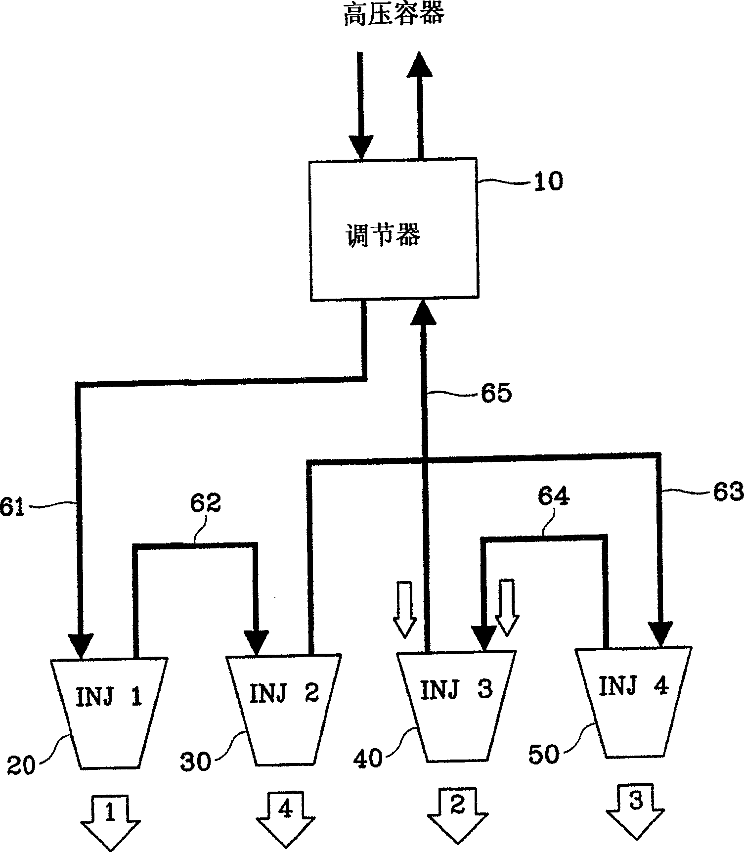
[0014] The preferred embodiment of the invention is used in a Liquefied Petroleum Injection (LPI) engine with four injectors arranged in a row. refer to figure 1 , the fuel supply system of the LPI engine includes a regulator 10, a first injector 20, a second injector 30, a third injector 40, a fourth injector 50 and a fuel hose 61 connected to the above components, 62, 63, 64, 65.

[0015] The regulator 10 keeps Liquefied Petroleum Gas (LPG), which is delivered by a pump at high pressure from a high-pressure vessel, at 5-10 bar at all times. The first to fourth injectors 20 to 50 are arranged consecutively, and in the order of the first injector 20, the third injector 40, the fourth injector 50 and the second injector 30 according to the control of the engine ECU Inject fuel.

[0016] The first fuel injector 20 receives fuel from the regulator 10 through the fuel hose 61 . The second fuel injector 30 receives fuel from the first fuel injector 20 through the second fuel ho...


PUM


Abstract

PROBLEM TO BE SOLVED: To provide a fuel hose connecting structure of a LPI engine to improve the durability not only by reducing the pulse noise of fuel but by reducing the heating of an engine control unit and an injection operating coil without cutting off the pressure fuel flow in the fuel hose for connecting a No.3 injector and a No.4 injector. SOLUTION: A No.1 injector receives fuel from a regulator via a first fuel hose. A No.2 injector receives fuel from the No.1 regulator via a second fuel hose. The No.4 injector receives fuel from the No.2 injector via a third fuel hose. The No.3 injector receives fuel from the No.4 injector via a fourth fuel hose, and returns fuel into the regulator via a fifth fuel hose. COPYRIGHT: (C)2006,JPO&NCIPI

Description

technical field [0001] The present invention relates to a fuel hose arrangement in a liquefied petroleum injection (LPI) engine. More specifically, the present invention relates to a fuel hose layout for connecting injectors of LPI engines. Background technique [0002] Typically, liquefied petroleum gas (LPG) is injected directly into the combustion chamber of a liquefied petroleum injection (LPI) engine. LPG with high evaporating properties is pumped from a high-pressure container through a fuel hose at about 5-10 bar. The LPG goes through a regulator and is then kept at 5-10 bar. If the pressure exceeds the above value, the regulator returns LPG to the high pressure vessel. [0003] When returning to the regulator, the LPG passes through the first through fourth injectors in succession. The ignition (in other words, injection) of the engine is performed in the order of the first, third, fourth and second injectors. [0004] In a conventional LPI engine, when LPG is s...

Claims


Application Information

Patent Timeline
Patent Type & Authority Patents(China)
IPC IPC(8): F02M55/02F02M21/02
CPCY02T10/32Y02T10/123Y02T10/12Y02T10/30F02M21/0236F02M37/0041
Inventor 徐有珍
Owner HYUNDAI BICYCLE
Why Eureka
Try Eureka