Check patentability & draft patents in minutes with Patsnap Eureka AI!

Actuator for an optical scanner

A technology of optical scanners and actuators, which is applied in the configuration/installation of the head, can solve the problem of the limitation of the number of tracks, and achieve the effect of reducing the sensitivity

Inactive Publication Date: 2009-10-14
THOMSON LICENSING SA
View PDF3 Cites 0 Cited by
  • Summary
  • Abstract
  • Description
  • Claims
  • Application Information

AI Technical Summary

Problems solved by technology

Therefore the number of orbitals is limited

Method used


Image

  • Actuator for an optical scanner
  • Actuator for an optical scanner
  • Actuator for an optical scanner

Examples


Embodiment Construction

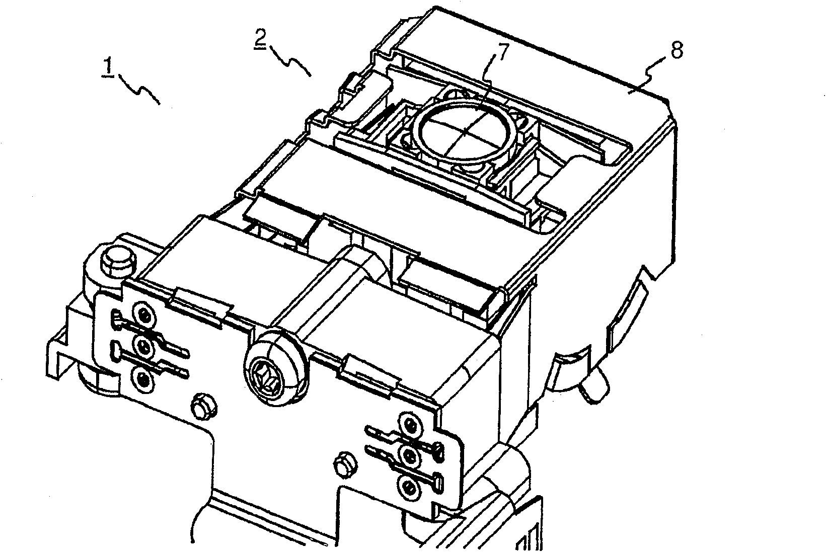
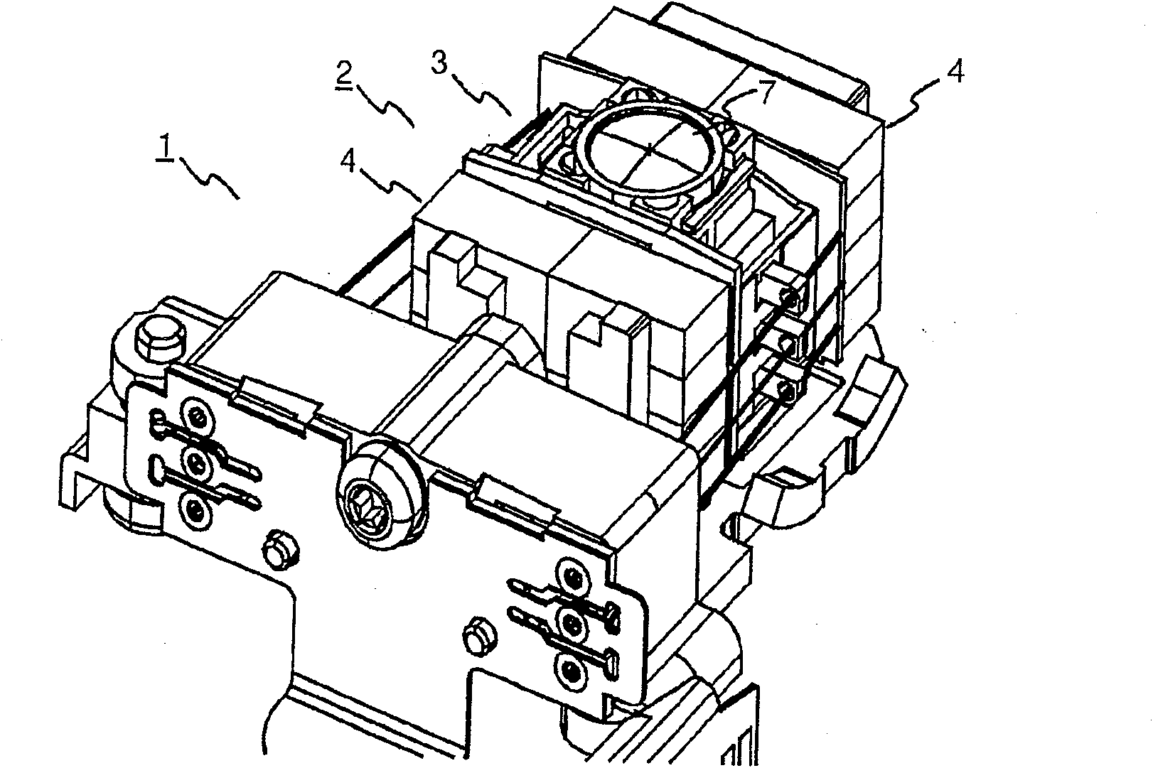
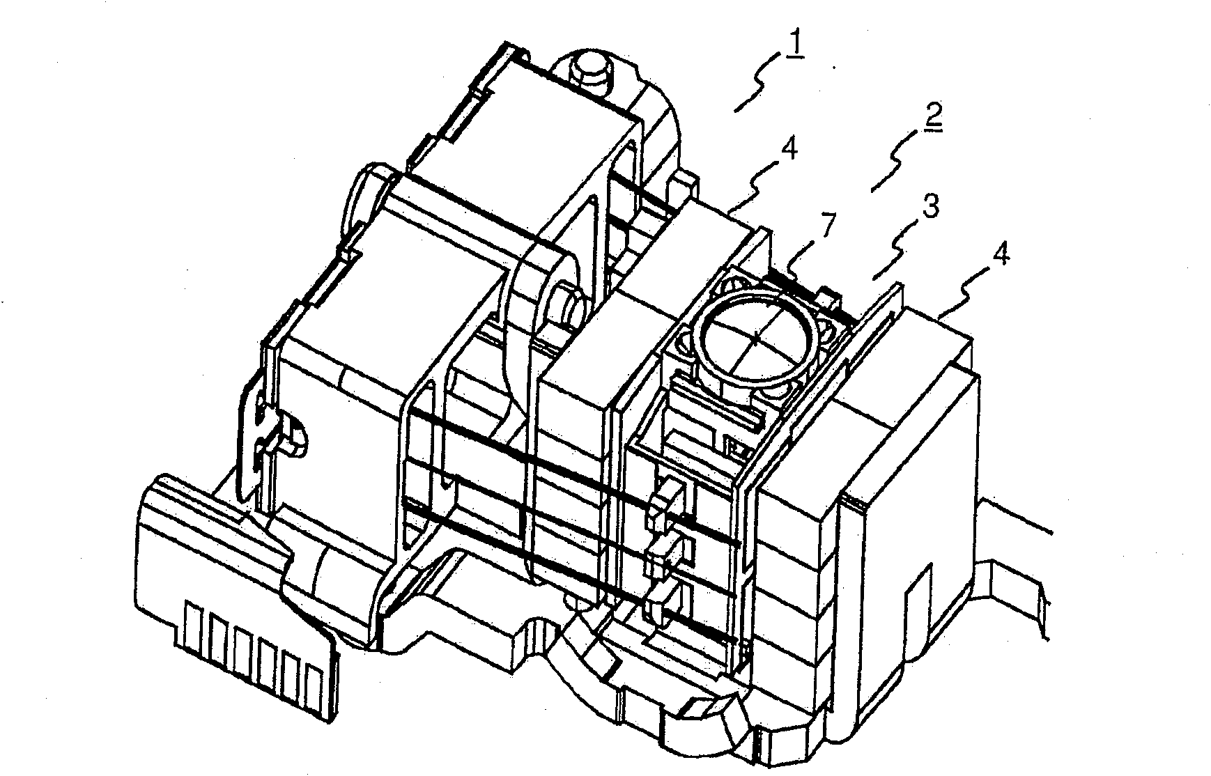
[0021] figure 1 A scanner 1 for an optical storage medium is shown, which uses an actuator 2 according to the invention for focus and tracking control by moving an objective lens vertically and horizontally. In the figure, the actuator 2 is partially concealed by a cover 8 . exist figure 2 The situation after removing the cover 8 of the optical scanner 1 is shown in . As can now be seen, the actuator 2 has a lens holder 3 for supporting the objective lens 7, and two magnets 4 for focusing and tracking control, which are arranged on one side of the lens holder 3 and associated printed coils 5, 6 interaction (in figure 2 cannot be seen in ). image 3 Views of the optical scanner 1 from different viewing angles are shown. The other elements of the optical scanner 1 are known to those skilled in the art and will not be explained in more detail here.

[0022] Figure 4 The lens holder 3 with the printed coil set 5, 6, ie the actuator 2 without the magnet 4 is shown. The ...


PUM


Abstract

The invention relates to an actuator (2) for an optical storage medium scanner, and a device for reading and / or writing on an optical storage medium using an actuator such as this. The invention proposes an actuator (2) for an optical scanner (1) with a lens holder (3) for supporting an objective lens (7) and printed coils (5, 6) for focus and tracking control , six printed coils (5, 6) are arranged on each of two opposing surfaces of the lens holder (3) and interact with associated magnets (4), each magnet having 16 poles.

Description

technical field [0001] The present invention relates to an actuator for an optical storage medium scanner, and a device for reading and / or writing on an optical storage medium using an actuator such as this. Background technique [0002] Actuators for optical scanners typically utilize wound coils combined with permanent magnets in order to focus the light beams used to read and / or write on the optical storage medium onto the information layer of the optical storage medium. In this case, the actuator controls the tracking and focusing of the focal point relative to the data track within the information layer of the optical storage medium. [0003] Printed coils are also used in actuators instead of wound coils. The printed coil is a printed circuit with printed copper tracks, ie the copper tracks run parallel to the magnets. Basically, the principle works the same way as winding a coil. Advantages of printed coils include ease of assembly of the actuator, elimination of w...

Claims


Application Information

Patent Timeline
Patent Type & Authority Patents(China)
IPC IPC(8): G11B7/09
Inventor 迈克尔·班默特铃木恒雄罗尔夫·杜珀
Owner THOMSON LICENSING SA
Features
  • R&D
  • Intellectual Property
  • Life Sciences
  • Materials
  • Tech Scout
  • Unparalleled Data Quality
  • Higher Quality Content
  • 60% Fewer Hallucinations
Learn More