Level shifter

A mover and level technology, applied in the field of microelectronics, can solve the problems of high power consumption and slow processing speed, and achieve the effects of reducing power consumption, increasing processing speed, and increasing conversion speed

Inactive Publication Date: 2009-11-18
VIMICRO CORP
View PDF4 Cites 0 Cited by
  • Summary
  • Abstract
  • Description
  • Claims
  • Application Information

AI Technical Summary

Problems solved by technology

[0007] The present invention provides a level shifter, which is used to solve the problems of slow processing speed and high power consumption during conversion of the level shifter in the prior art

Method used


Image

  • Level shifter
  • Level shifter
  • Level shifter

Examples


Embodiment Construction

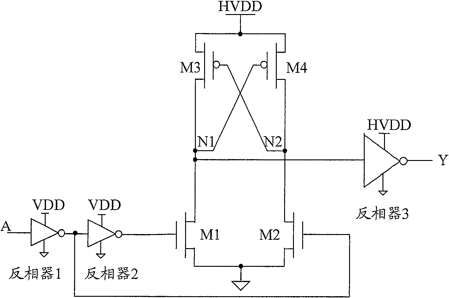
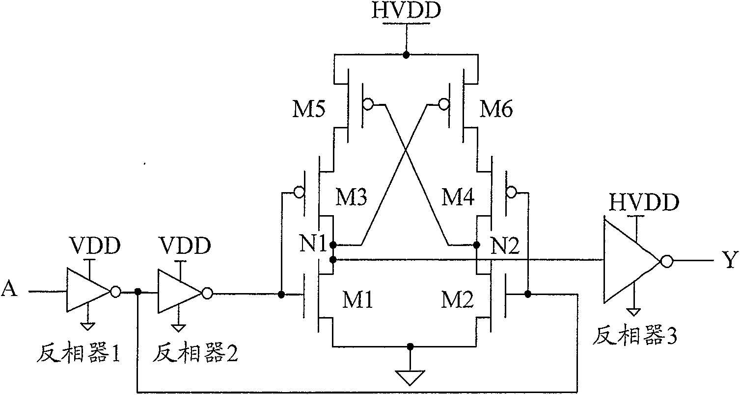
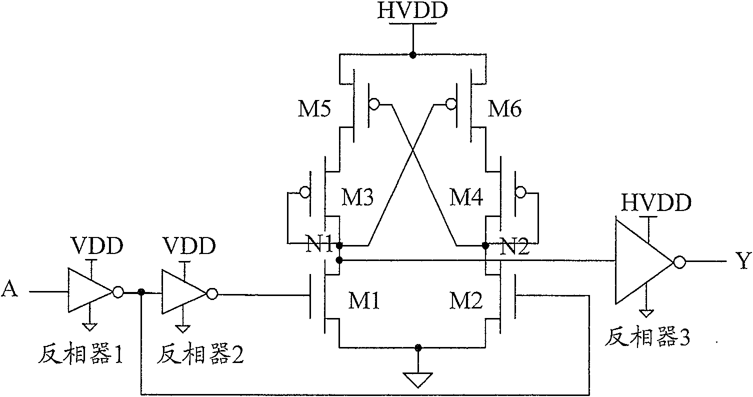
[0024] In order to solve the problems of slow processing speed and high power consumption during conversion in the level shifter in the prior art, in the embodiment of the present invention, in the two groups of circuits of the level shifter, the current limiting circuit in each group of circuits is The gate of the MOS transistor is connected to the drain to realize a high-speed, low-power level shifter.

[0025] The level shifter in the embodiment of the present invention includes first and second groups of circuits; wherein, each group of circuits includes a switch circuit and two MOS transistors;

[0026] In each group of circuits, the gate of the first MOS transistor is connected to the drain, and the source is connected to the drain of the second MOS transistor; the source of the second MOS transistor is connected to the second power supply; the second MOS transistor in each group of circuits The gate of the gate is connected to the drain of the first MOS transistor in an...


PUM


Abstract

A level shifter consists of the first set and the second set of circuits. It is featured as forming each set of circuit by a switch circuit and two MOS tubes, connecting source electrode of the second MOS tube to the second power supply, controlling on-off of switch circuit by input signal based on the first power supply and outputting an output signal based on the second power supply by the first MOS tube in the first set circuit after drain electrode of said first MOS tube is phase-inversed.

Description

technical field [0001] The invention relates to the technical field of microelectronics, in particular to a level shifter. Background technique [0002] The common CMOS level shifter has the characteristics of fast speed and small area, and is often used in digital-analog hybrid circuits. Generally, refer to figure 1 As shown, its components include: high-threshold MOS transistors M1-M4, inverters 1-2 composed of low-threshold MOS transistors, and inverter 3 composed of high-threshold MOS transistors. The function of the level shifter is to convert the input signal A whose logic level is VDD-0 into the output signal Y whose logic level is HVDD-0, wherein HVDD is greater than VDD. [0003] figure 1 , assuming the initial state: input signal A is logic 0, M1 is off, M2 is on, N1 node voltage is HVDD level value, N2 node voltage is 0 level value, M3 is on, M4 is off. When the input signal A changes from logic 0 to logic 1, the gate voltage of M1 also changes from logic 0 to ...

Claims


Application Information

Patent Timeline
Patent Type & Authority Patents(China)
IPC IPC(8): H03K19/0185H03K3/356
Inventor 温婷婷
Owner VIMICRO CORP
Why Eureka
Try Eureka