Centrifugal compressor having air removal jet box structure

A centrifugal compressor and compressor technology, which is applied to machines/engines, components of pumping devices for elastic fluids, mechanical equipment, etc., can solve problems such as stall flow loss, unstable compressor operation, large flow loss, etc. , to achieve the effect of suppressing flow separation, improving stall margin and efficiency

Inactive Publication Date: 2007-08-08
TSINGHUA UNIV
View PDF0 Cites 20 Cited by
  • Summary
  • Abstract
  • Description
  • Claims
  • Application Information

AI Technical Summary

Problems solved by technology

However, under the condition of low flow rate, the increase of the angle of attack of the blade airflow makes the boundary layer of the suction surface of the impeller blade thicker, and further large-scale flow separation occurs under the action of the reverse pressure gradient, resulting in the generation, development and development of large-scale vortices. Broken, accompanied by large flow loss; when the flow rate is further reduced, the separation will be more serious, which will lead to unstable operation of the compressor, resulting in stall or even surge
When the flow rate is small, large-scale flow separation also occurs on the casing wall inside the diffuser, which will cause stall and increase flow loss, and even surge

Method used


Image

  • Centrifugal compressor having air removal jet box structure
  • Centrifugal compressor having air removal jet box structure
  • Centrifugal compressor having air removal jet box structure

Examples


Embodiment Construction

[0015] The specific embodiment of the present invention will be described with reference to the accompanying drawings.

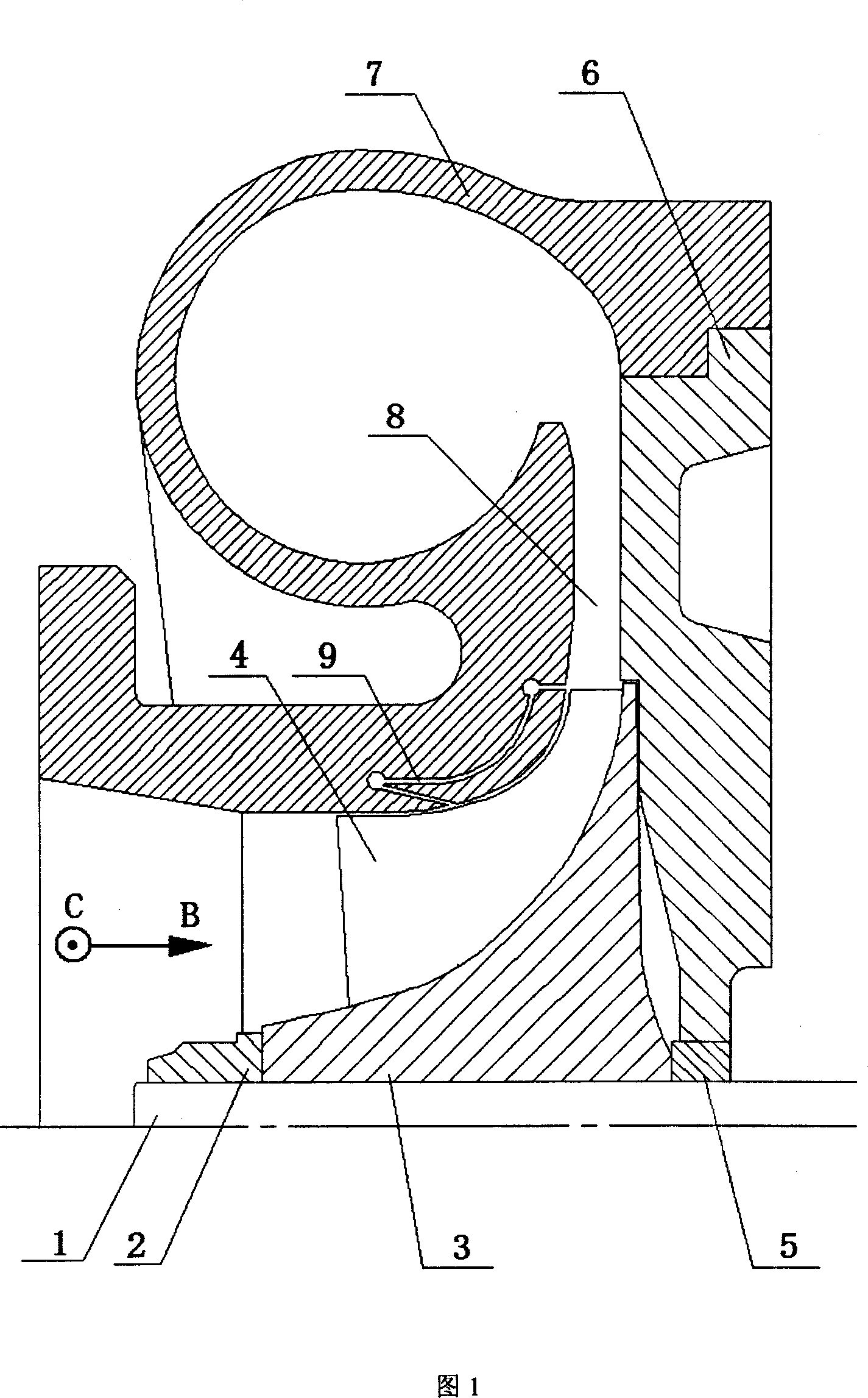
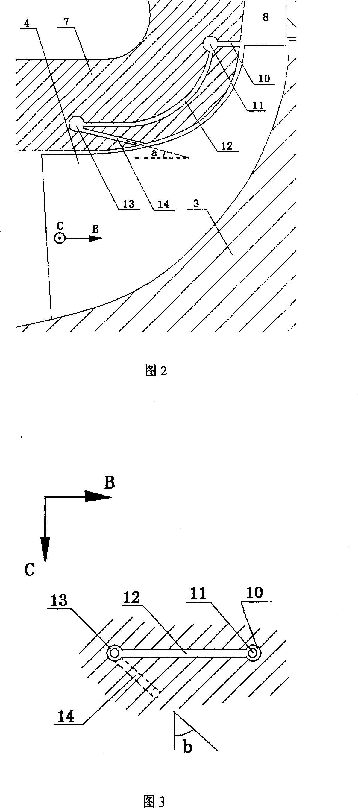
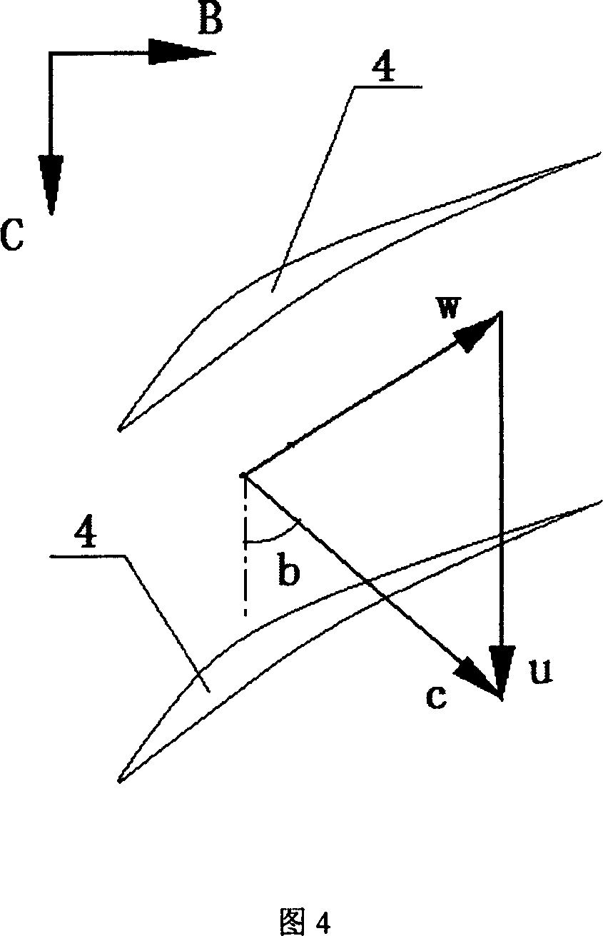
[0016] As shown in Figure 1, compressor shaft 1, impeller fixing bolts 2, impeller 3, blade 4 on impeller 3, sealing block 5, impeller back plate 6, volute 7, all are common parts of existing compressors, without blades The diffuser channel 8 is formed by the combination of the impeller back plate 6 and the volute 7 . The inlet flow direction is B, and the compressor impeller 4 rotation direction is C. The present invention is characterized in that no less than three air extraction-jet flow guide passages 9 are opened on the casing wall of the volute 7, and each air extraction-jet flow guide passage 9 is uniformly distributed around the compressor shaft 1 as the center. , the suction hole at the back end of the diversion channel is opened at the casing wall of the inlet of the vaneless diffuser 8, the jet hole at the front end is opened at the maximum twist...


PUM


Abstract

A centrifugal compressor with an air-bleed and a jetting box construction belongs to the turbo-machine field. The invention is characterized in that the wall of the box of worm frame is arranged with at least three exhaust-injection guide channels uniformly arranged around the rotary axle of compressor, while it contains exhaust channels and injection channels. The opening of the exhaust channels is arranged at the wall at the inlet of the non-blade expander channel, and vertical to the wall of inlet box. The opening of the injection channel is at the most torsion of the channel formed by the worm frame and blade, while it is at same direction of main absolute speed of most torsion. The exhaust channel and the injection channel are connected via the guide channel. The inventive exhaust-injection guide channel can exhaust the adhere layer at the wall of expander, restrain the flow separation of expander, and fill high-energy injection into the channel of blade wheel, to restrain the flow separation of adsorption face and restrain the flow separation at small flux, to improve the speed-lost allowance and efficiency.

Description

Technical field: [0001] A centrifugal compressor with an air extraction and jet casing structure belongs to the technical field of impeller machinery, and relates to the improvement of impeller machinery casings such as centrifugal compressors for vehicle and marine superchargers, industrial centrifugal compressors, and aviation centrifugal compressors. technical background: [0002] Compared with the reciprocating compressor, impeller compressors such as centrifugal compressors have the advantages of high efficiency, light volume and weight, and stable operation, but their working conditions are limited. Under the low flow condition of the centrifugal compressor, there will be large-scale flow separation in the impeller and diffuser, resulting in unstable operation, stalling or even surge, which will directly lead to a sharp drop in compressor efficiency and pressure ratio, and a serious shortening of life. , or even directly damaged in a short period of time. [0003] The...

Claims


Application Information

Patent Timeline
Patent Type & Authority Applications(China)
IPC IPC(8): F04D17/08F04D29/42
CPCF04D29/685F04D29/4206
Inventor 张扬军郭宫达郑新前徐建中诸葛伟林杨名洋
Owner TSINGHUA UNIV
Why Eureka
Try Eureka