Microjet forming method for controlling leakage flow of rotor blade tip of gas compressor

A compressor rotor and leakage flow technology, which is applied to the components of pumping devices for elastic fluids, mechanical equipment, machines/engines, etc., can solve the problem of centrifugal force affecting rotor blade strength, etc. Efficiency, the effect of reducing flow loss

Pending Publication Date: 2020-07-10
NANJING UNIV OF AERONAUTICS & ASTRONAUTICS
View PDF6 Cites 0 Cited by
  • Summary
  • Abstract
  • Description
  • Claims
  • Application Information

AI Technical Summary

Problems solved by technology

Suction at the tip of the blade requires an additional suction device; the blade tip winglet produces a large centrifugal force that affects the strength of the rotor blade

Method used


Image

  • Microjet forming method for controlling leakage flow of rotor blade tip of gas compressor
  • Microjet forming method for controlling leakage flow of rotor blade tip of gas compressor
  • Microjet forming method for controlling leakage flow of rotor blade tip of gas compressor

Examples


Embodiment Construction

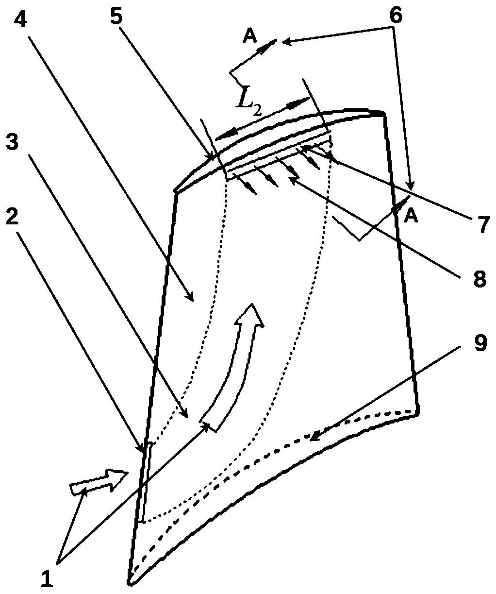
[0016] The following combination Figure 1 to Figure 4 The present invention uses centrifugal force and velocity impulse to form a micro jet to control the implementation method of compressor rotor blade tip leakage flow.

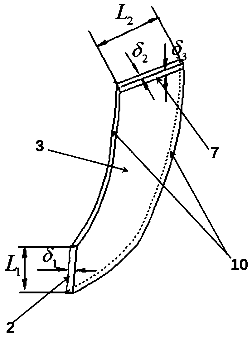
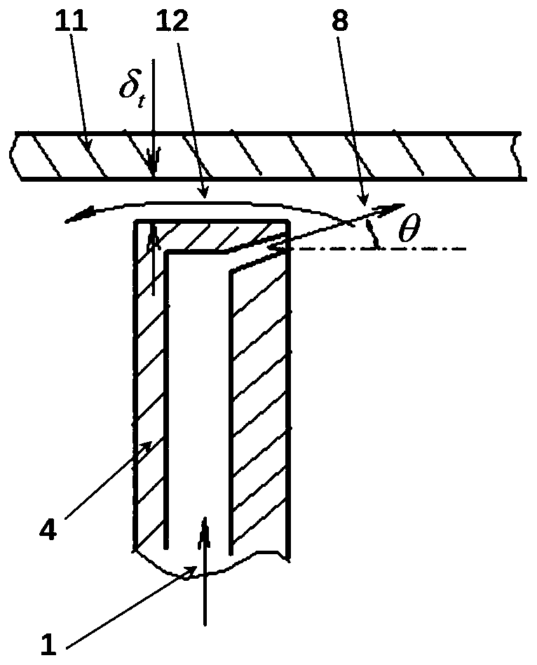
[0017] A method for controlling the leakage flow of a compressor rotor blade tip by using centrifugal force and velocity impulse to form a micro-jet. The slit is connected to the hollow chamber. The high-speed rotating compressor rotor inhales gas, most of which flows into the vane passage. From the perspective of relative motion, standing on the rotor blade, the air flow flows through the rotor blade at high speed, in which the trace gas 1 flows into the gap 2 at the leading edge of the blade, moves from the blade root to the blade tip through the blade hollow chamber 3 under the action of centrifugal force, and is transported by the blade The pointed slit 7 flows out, forming a micro-jet 8. The blade tip gap can be opened on the side of the blade tip c...


PUM


Abstract

The invention discloses a microjet forming method for controlling leakage flow of the rotor blade tip of a gas compressor. The method is characterized in that a hollow cavity used for enabling the blade front edge to communicate with the blade tip is formed in a rotor blade, a blade front edge gap is formed in the position, close to the blade root, of the rotor blade and communicates with the hollow cavity, and a gap is formed in the top of the rotor blade and communicates with the hollow cavity; a rotor rotates at a high speed to suck gas inwards, and most of the gas flows into a blade channel; and trace gas flows into the blade front edge gap, moves from the blade root to the blade tip through the hollow cavity of the blade under the action of centrifugal force, and flows out from the blade tip gap to form a microjet. The method for forming the microjet and controlling the leakage flow of the rotor blade tip gap by means of centrifugal force acting and speed impulse can be used for axial flow compression machines such as an air compressor and a fan so as to reduce flow loss, improve the efficiency and enlarge the stall margin.

Description

technical field [0001] The invention belongs to the technical field of aerodynamics, and relates to the flow control technology of an axial flow compressor and a fan, in particular to a compressor rotor blade which utilizes centrifugal force and velocity impulse to form micro jets to control blade tip leakage flow. Background technique [0002] The axial compressor and fan rotors are rotating parts with tip clearances from the stationary outer casing. The blade tip clearance causes the leakage flow of the blade tip clearance, which produces a large flow loss and is also the main reason for the flow stall; the higher the pressure ratio of the compressor and the fan stage, the greater the impact. In order to improve the thrust-to-weight ratio of aero-engines, aero-compressors and fans are always developing toward higher pressure ratios. Therefore, for aerospace compressors and fans, it is more valuable to control the tip clearance leakage flow. [0003] In January 2020, Zhan...

Claims


Application Information

Patent Timeline
Patent Type & Authority Applications(China)
IPC IPC(8): F04D29/38
CPCF04D29/388
Inventor 周正贵叶新龙郑欢
Owner NANJING UNIV OF AERONAUTICS & ASTRONAUTICS
Why Eureka
Try Eureka