Cavity supporting plate flame stabilizer with built-in oil rod

A flame stabilizer and concave cavity technology, applied in the combustion method, combustion chamber, combustion equipment and other directions, can solve the problems of limiting the performance of the concave cavity support plate flame stabilizer, achieve good atomization effect, simple structure, reduce infrared effect of radiation

Inactive Publication Date: 2015-02-25
BEIHANG UNIV
View PDF6 Cites 15 Cited by
  • Summary
  • Abstract
  • Description
  • Claims
  • Application Information

AI Technical Summary

Problems solved by technology

However, in this scheme, the flame stabilizer and fuel injection system are still independent of each other, which limits the performance of the flame stabilizer with concave cavity support plate

Method used


Image

  • Cavity supporting plate flame stabilizer with built-in oil rod
  • Cavity supporting plate flame stabilizer with built-in oil rod
  • Cavity supporting plate flame stabilizer with built-in oil rod

Examples


Embodiment Construction

[0025] The present invention will be described in detail below in conjunction with the accompanying drawings and specific embodiments.

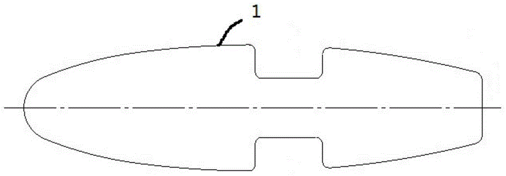
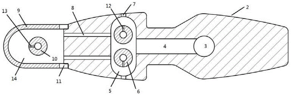
[0026] According to an embodiment of the present invention, for the concave cavity support plate flame stabilizer 1 proposed in the Chinese patent application No. 201010135627.X (see figure 1 ) was modified and designed, and the head structure of the original concave cavity support plate flame stabilizer was canceled and replaced by such figure 2 The shown scheme includes a semi-strip-shaped front baffle 9 , and the front baffle 9 is welded together with the cavity support plate 2 . Simultaneously, two cavities are designed inside the original solid concave cavity support plate, i.e. the rear cavity 3 and the front cavity 5, and there are two circular connecting passages 4 ( figure 2 Only one of them is shown in ) to connect.

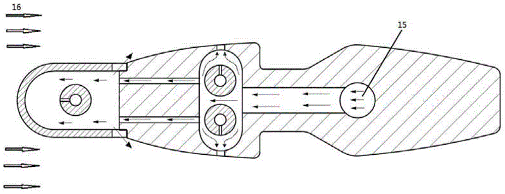
[0027] In the integrated design of the fuel injection system and the concave cavity support plate according to t...


PUM


Abstract

The invention provides an integrated design scheme of an oil injection system and a cavity supporting plate flame stabilization device, and discloses a cavity supporting plate flame stabilizer with a built-in oil rod. An oil injection rod is arranged in an inner cavity of a cavity supporting plate in a built-in mode, in this way, the number of components of an afterburner can be decreased, flow losses caused by the components are lowered, and the overall performance of the afterburner is improved. Meanwhile, the built-in oil injection rod can be subjected to pneumatic nebulization through cooling airflow which flows past the inside of the cavity supporting plate. Compared with a traditional direct-injection type oil injection mode, the atomization effect is better, and the organization burning capacity of the flame stabilizer and the combustion efficiency of the afterburner are further improved.

Description

technical field [0001] The invention relates to a novel integrated flame stabilizing device for an afterburner in a gas turbine engine. The fuel injection system is built in the flame stabilizer to realize the integrated design of fuel injection and flame stabilization. Background technique [0002] The afterburner is one of the essential components of modern military engines. By re-injecting fuel into the gas after the turbine, the remaining oxygen in the gas after the turbine is further organized and burned, which can greatly increase the thrust of the engine in a short time. However, the gas velocity at the turbine outlet is very fast, so the circumferential and radial blunt body flame stabilizers are generally arranged in the afterburner, and the high-speed air flow bypasses the recirculation zone formed by the blunt body structure to stabilize the flame and organize combustion. However, this solution has obvious disadvantages. When the engine is not working in the after...

Claims


Application Information

Patent Timeline
Patent Type & Authority Applications(China)
IPC IPC(8): F23R3/60F23R3/18
Inventor 金捷王方刘邓欢刘玉英岳明
Owner BEIHANG UNIV
Why Eureka
Try Eureka