Double cam axial engine with over-expansion, variable compression, constant volume combustion, rotary valves and water injection for regenerative cooling

a double cam axial engine and variable compression technology, which is applied in the direction of reciprocating piston engines, engines, positive displacement engines, etc., can solve the problems of internal combustion engines that are theoretically less efficient at partial throttle settings, damage and eventual failure, and reduce compression work, increase compression ratio, and increase compression ratio

Inactive Publication Date: 2015-11-24
MNC ENG
View PDF17 Cites 8 Cited by
  • Summary
  • Abstract
  • Description
  • Claims
  • Application Information

AI Technical Summary

Benefits of technology

[0016]In accordance with another aspect of the invention, there is provided an axial engine having up to three direct (in-cylinder) water injection cycles and a further possible extra injection into the intake manifold for each cylinder during each four stroke events. A first water injection occurs during compression wherein the water is used to cool the air / fuel mixture. This reduces compression work and allows an increase in the compression ratio. A second water injection takes place during combustion (start of piston dwell at TDC) and is used to cool the combustion process itself. This eliminates the need for Exhaust Gas Recirculation (EGR) and enables higher compression ratios. A third water injection (onto the various walls) takes place during expansion (after combustion occurs) and provides for the internal cooling of the combustion chamber, piston and the rotary valves. This allows for what we call internal regeneration, where part of the heat that would be lost to the engine walls is retrieved to produce work by the expansion of the liquid water into vapor. Also the wall temperature inside the engine will be decreased and controlled by the water fuel ratio and water injection duration. This eliminates hot spots reducing the onset of knock.
[0017]The water injection into the intake manifold reduces air temperature and increases its density, increasing volumetric efficiency. The net effect of the total water injection is an increase in fuel efficiency, through compression work reduction, compression ratio increase and regeneration of the heat transferred to the walls. The interior of the combustion walls should be maintained between 250 to 300 degrees Centigrade to provide adequate vapor pressure for the regenerative cooling. The calculated water to fuel ratio is preferably 4.3:1 at idle and 1.4:1 at Wide Open Throttle (WOT) but may vary from 0:1 to 7:1. While this is an open loop process (the water is lost via the exhaust) a substantial amount, up to 66% of the total water in the exhaust, may be recovered and recycled via, for example, a capillary condensation pore process as described in U.S. Pat. No. 8,511,072, issued Aug. 20, 2013 and herein incorporated by reference in its entirety.
[0018]In accordance with the combined aspects of the invention, there is provided an axial engine having improved thermodynamic efficiency. A thermodynamic analysis using Converge CFD and MATLAB® SIMULINK® engine models predict an increase in fuel efficiency ranging from 50 percent to 72 percent, achieving a 45 percent mark in overall efficiency. In particular, compared to a conventional SI engine with a 30 percent efficiency at WOT, the axial engine according to the present invention may reach an efficiency of 45 percent, which is a 50 percent improvement, the improvement provided given by water injection (21 percent), Constant Volume Combustion (CVC) (7 percent), over-expansion (12 percent), improved combustion / compression ratio (5 percent), and reduced friction losses (5 percent). Further, compared to a conventional SI engine with a 25 percent efficiency at partial load, the axial engine according to the present invention may reach an efficiency of 43 percent, which is a 72 percent improvement, given by water injection (17 percent), CVC (13 percent), over-expansion (7 percent), improved combustion / compression ratio (27 percent), and reduced friction losses (8 percent). Further, compared to a conventional SI engine, which has a 180 degree power stroke for 720 degrees of output shaft revolution, the axial engine has a 90 degree power stroke for 90 degrees of output shaft revolution.

Problems solved by technology

Higher compression ratios for street driven automobiles would increase the thermodynamic efficiency, and thus the gas mileage, but also results in detonation in the combustion chambers of the engines resulting in damage and eventual failure.
Internal Combustion Engines (ICE) are theoretically less efficient at partial throttle settings then when running wide open due to parasitic losses, etc.
Thermodynamic theory suggests, that a heat engine of this type may achieve an efficiency factor of about 60-65 percent at best, but known engines are far from that, and 70 percent of the energy available in a gallon of gasoline is wasted.
However, these small incremental changes have become few and far between and more costly.
Compressing the AFM takes a large amount of energy which reduces the power output.
So the AFM is burning before TDC and is getting hotter and pressure in the cylinder is rising over and above that caused by the compression process itself, which increases the negative work.
Gas engines are limited in the compression ratio because of a phenomenon called detonation or knock.
Detonation occurs because the compression ratio is so high and the combustion chamber wall so hot that the self-ignition temperature of the AFM is reached causing combustion.
These are untimed events that often seriously damage the engine.
In summary, most of the energy in a gallon of gasoline is wasted.
Even an ideal known SI engine will only recover another third of the energy in the gasoline burned by the engine, two revolutions of the crankshaft are required to produce ½ revolution of power, the piston strokes (all of them) are of equal and fixed length, wasting energy remaining in the cylinder at the end of the power stroke, and higher compression ratios which provide greater thermodynamic efficiency are not possible due to detonation.

Method used


Image

  • Double cam axial engine with over-expansion, variable compression, constant volume combustion, rotary valves and water injection for regenerative cooling
  • Double cam axial engine with over-expansion, variable compression, constant volume combustion, rotary valves and water injection for regenerative cooling
  • Double cam axial engine with over-expansion, variable compression, constant volume combustion, rotary valves and water injection for regenerative cooling

Examples


Embodiment Construction

[0044]The following description is of the best mode presently contemplated for carrying out the invention. This description is not to be taken in a limiting sense, but is made merely for the purpose of describing one or more preferred embodiments of the invention. The scope of the invention should be determined with reference to the claims.

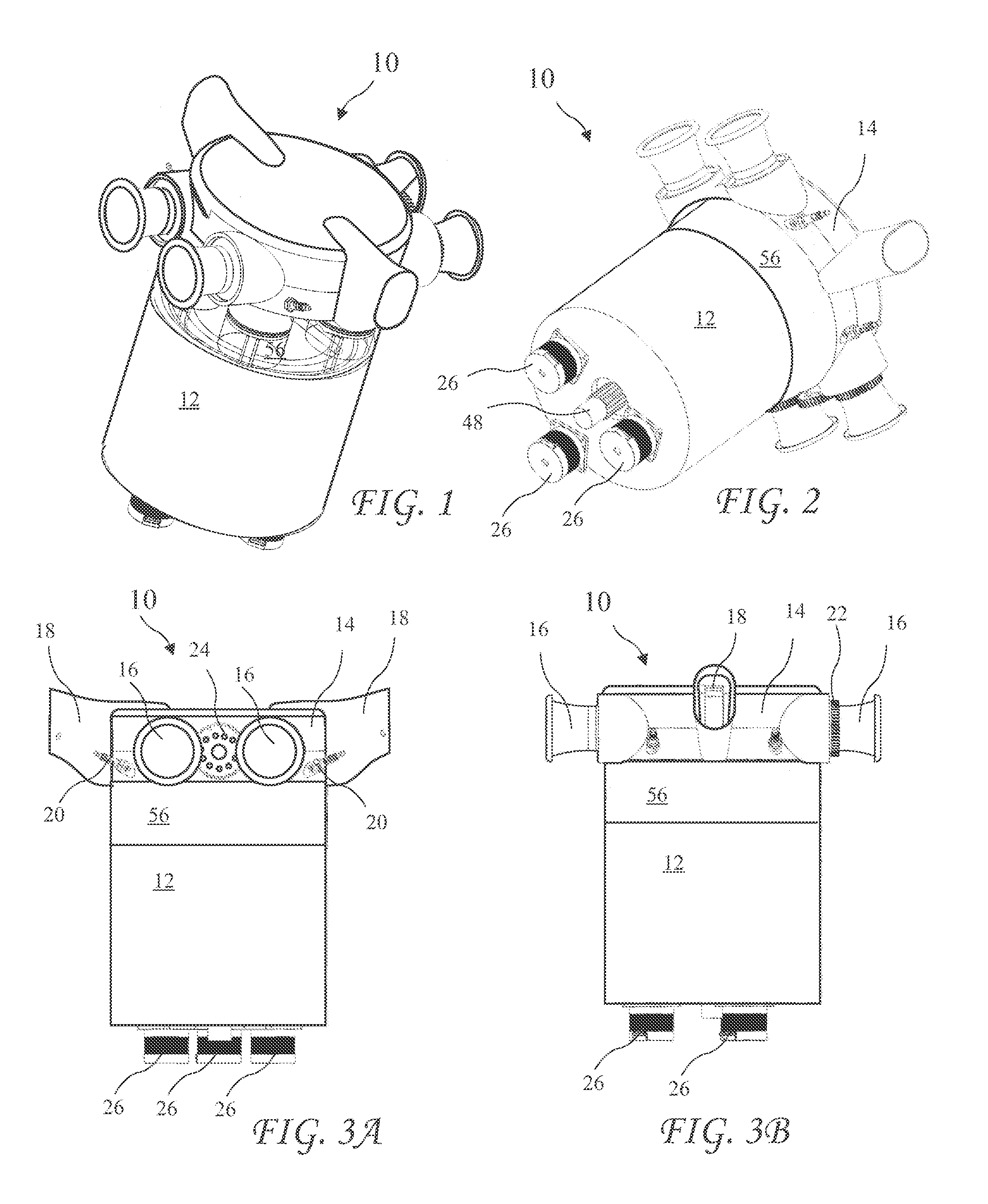
[0045]A top and side perspective view of an axial engine 10 according to the present invention is shown in FIG. 1, a bottom and side perspective view of the axial engine 10 is shown in FIG. 2, a first side view of the axial engine 10 is shown in FIG. 3A, and a second side view of the axial engine 10 is shown in FIG. 3B. The axial engine 10 includes a head 14 fixed to a cylinder block 56. An engine housing 12 is fixed to the cylinder block 56 opposite to the head 14. The cylinder head 14 includes air intakes 16, exhaust headers 18, spark plugs 20, and a rotary valve drive gear 24. Other preferred elements of the head 14 are shown in FIGS. 15-18. Se...


PUM


Abstract

An axial engine includes a cam assembly housing moveable away from a cylinder head to reduce a compression ratio during conditions giving rise to detonation and movable towards the cylinder head to raise the compression ratio when operation allows the higher compression ratio. Piston rod ends ride in counter rotating slots balancing lateral forces on the piston rods. Piston dwell at Top Dead Center (TDC) provides for constant volume combustion and extended piston travel during the power stroke allows for over-expansion. Rotary valves improve volumetric efficiency and water injection supports increased compression ratio leading to improved thermodynamic efficiency.

Description

CROSS-REFERENCE TO RELATED APPLICATIONS[0001]The present application claims the priority of U.S. Provisional Patent Application Ser. No. 62 / 123,710 filed Nov. 11, 2014, which application is incorporated in its entirety herein by reference.BACKGROUND OF THE INVENTION[0002]The present invention relates to internal combustion engines and in particular to a crankless over-expanded variable-compression engine with regenerative internal-cooling using constant-volume combustion and rotary-valves.[0003]The thermodynamic efficiency of an internal combustion engine is strongly related to a compression ratio of the engine. Typical automotive engines have compression ratios of 8.5:1 to 12:1 for street driven automobiles, and sometimes higher for racing engines using special racing fuel in racing conditions. Higher compression ratios for street driven automobiles would increase the thermodynamic efficiency, and thus the gas mileage, but also results in detonation in the combustion chambers of th...

Claims


Application Information

Patent Timeline
Patent Type & Authority Patents(United States)
IPC IPC(8): F02B75/04F02B75/26F01B3/00F01B3/02
CPCF02B75/26F02B75/041F01B3/0026F01B3/02F01B3/101F01B3/102F02B41/04F02B47/02F02B75/04F02B2275/36Y02T10/12
Inventor BON, BERNARDMARTINS, JORGEBRITO, FRANCISCOCOSTA, TIAGO
Owner MNC ENG
Why Eureka
Try Eureka