System of energy efficiency for refrigeration cycle

a technology of energy efficiency and refrigeration cycle, applied in the field of refrigeration cycle, can solve the problems of increasing electric power consumption, phase change of refrigerant, and poor coefficient of performance, and achieve the effects of reducing the volume of fresh gas, reducing the temperature of liquid refrigerant, and reducing the high pressure and medium temperatur

Inactive Publication Date: 2006-09-07
HAN MYUNG BUM
View PDF5 Cites 15 Cited by
  • Summary
  • Abstract
  • Description
  • Claims
  • Application Information

AI Technical Summary

Benefits of technology

[0023] According to the present invention, the pressure support valve maintains the condensed pressure of the gas refrigerant compressed into high pressure and high temperature refrigerant by compressor. The pressure of the liquid refrigerant having high pressure and medium temperature is decreased properly. The liquid having medium pressure and medium temperature and the gas refrigerant having low pressure and low temperature are inter-heat-exchanged at the insulated duplex pipe of the heat exchanger unit. Thus, the temperature of the liquid refrigerant can be significantly decreased. The vapor refrigerant is superheated.
[0024] Therefore, the volume of fresh gas is considerably reduced after the expansion of the liquid refrigerant, and the volume of absorption of the evaporation latent heat is increased. The condensed pressure is slightly reduced by the heat exchanger unit and the discharge pressure of the compressor is lessened, thus decreasing the compression work.
[0025] The present invention increases the refrigeration effect and coefficient of performance and decreases consumption of electric power. It leads to the performance improvement of heating / cooling of the heat pump.

Problems solved by technology

As well known, a refrigeration cycle changes the temperature and pressure in a system and can lead to a phase change of refrigerant.
However, if the refrigeration effect has increased above the increment along the increase of the compression work, coefficient of performance is rather worse or the consumption of electric power is increased.
Coefficient of performance must be improved adequate to the system considering various matters such as a property of refrigerant.
Specially, during heating operation in winter, the refrigerant cannot sufficiently absorb the latent heat of the evaporation due to the low outdoor temperature, causing the evaporation inferiority.
The degree of dry saturation of the refrigeration having low pressure is decreased and it leads to the occurrence of the compression inferiority owing to the wet compression.
It is hard to expect the sufficient heating performance.
Moreover, overload is imposed on the compressor to cause the burnout.
The consumption of electric power is increased by the large work capacity.
However, the third heat recovery apparatus is provided between the compressor and the 4-way valve in the heat pump system, the refrigerant having low pressure is flowing into the compressor with excessive heat when in cooling, and that system is very concerned about damage due to the superheating in the compressor.
Not enough heating is anticipated.
However, under the constant pressure, the liquid refrigerant having high pressure is simply dependent on thermal conduction, and it makes the degree of super-cooling to be lowered, and the volume decrease of flash gas of the expanded refrigerant is very slight.
However, in this technology, the liquid refrigerant having high pressure does heat conduction at medium temperature under condensed pressure, and it causes a low degree of super-cooling.
Therefore, the evaporation of heating operation is still inferior in winter.
Further, the quantity of conduction heat is very low comparing to vapor since the liquid refrigerant is simply dependent on heat conduction.
More, due to the non-insulation of the heat exchanger, most heat of the liquid refrigerant is released to the air during the heat exchange process, which leads to very low degree of the super-heating of the gas refrigerant having low pressure.
Therefore, it is hard to anticipate a decrease of compression load and to accomplish a deduction of consumption of electric power.
Specially, no sufficient heating is expected due to lack of the heat capacity when in heating.

Method used


Image

  • System of energy efficiency for refrigeration cycle
  • System of energy efficiency for refrigeration cycle
  • System of energy efficiency for refrigeration cycle

Examples


Embodiment Construction

[0038] This invention will be described in further detail by way of exemplary embodiments with reference to the accompanying drawings.

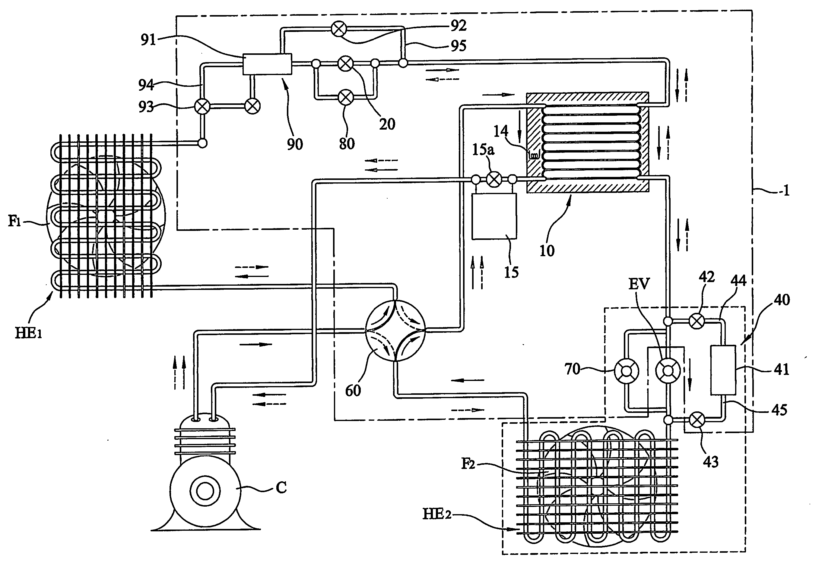
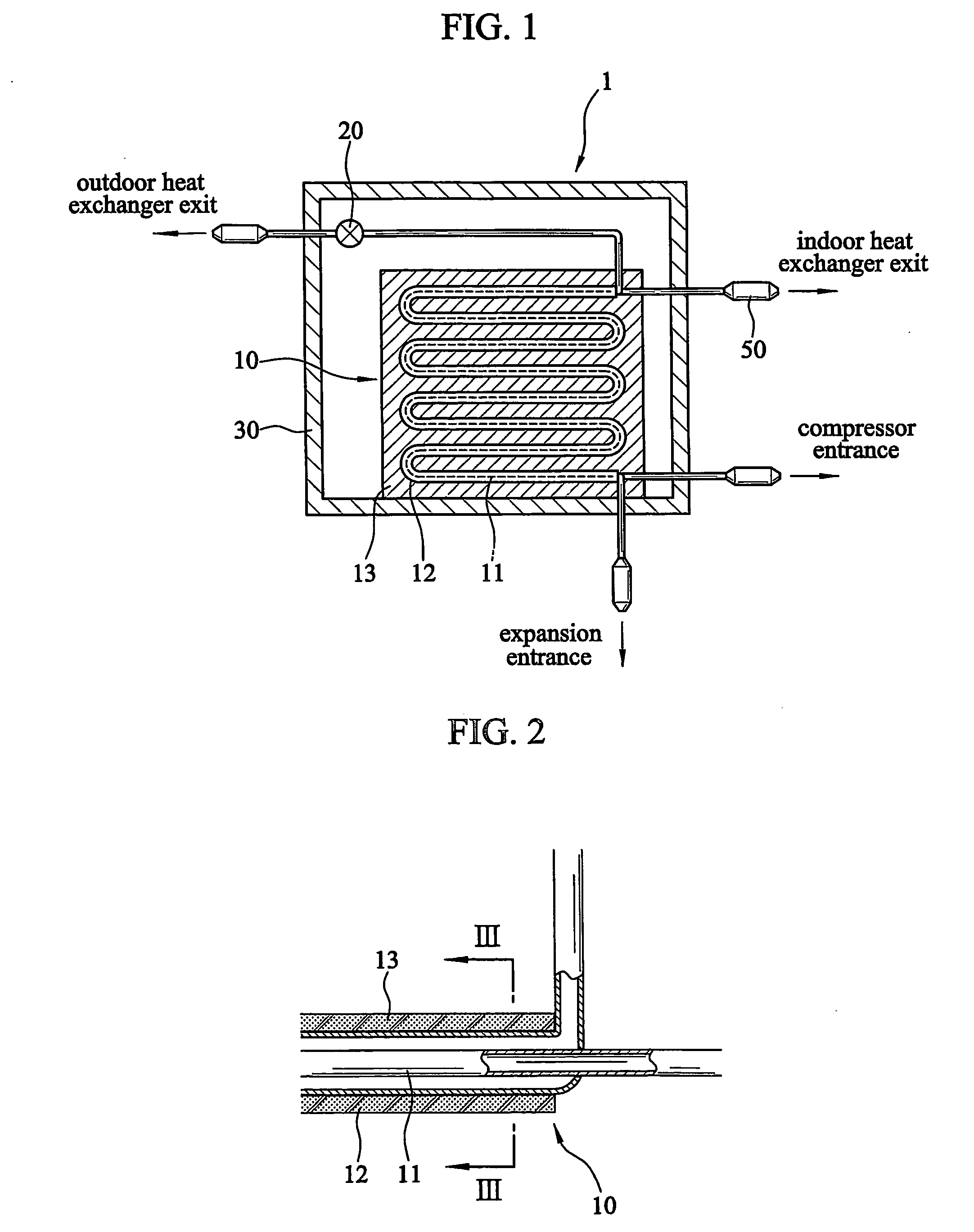
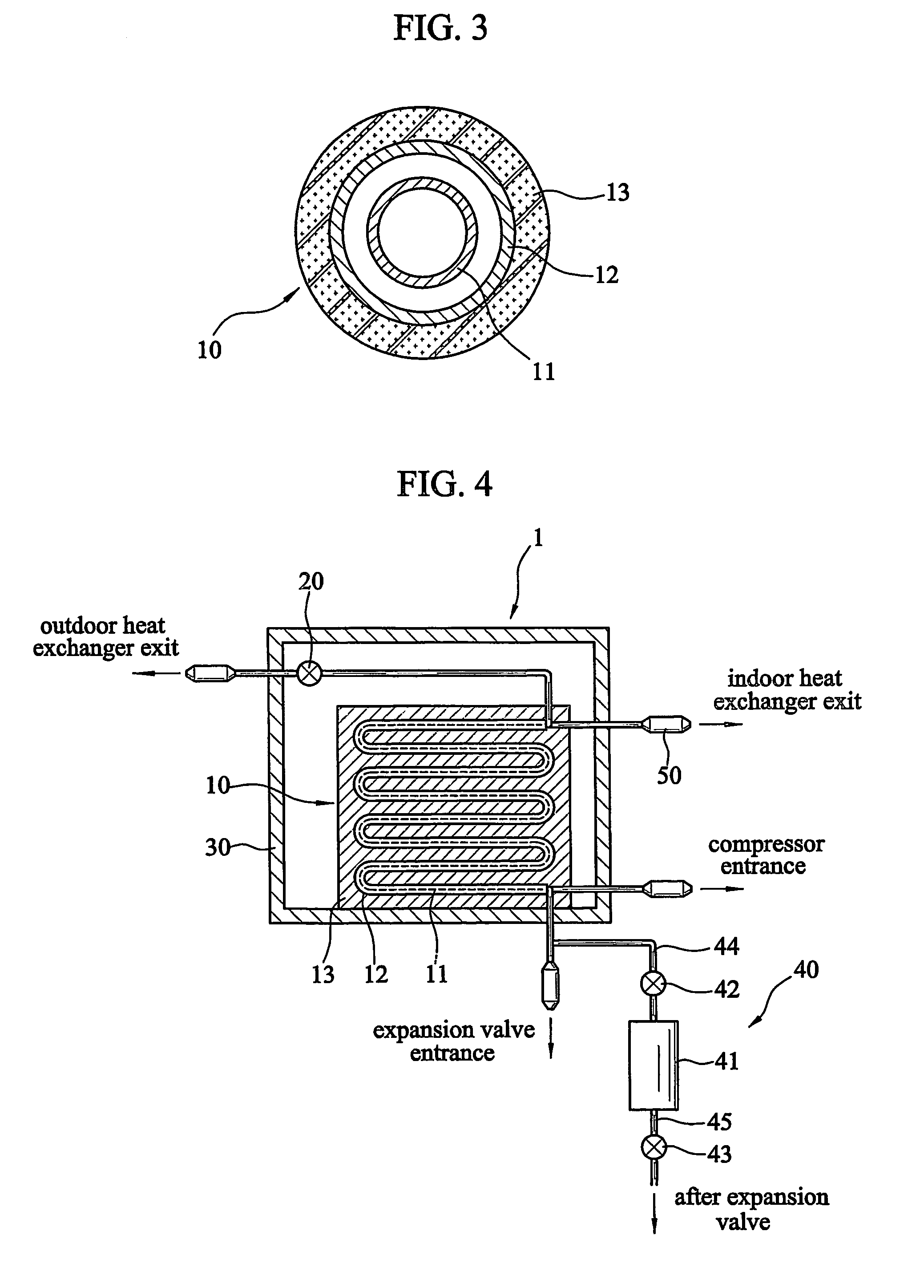
[0039] In FIGS. 1, 2 and 3, improvement system of energy efficiency for the refrigeration cycle 1 basically comprises an auxiliary heat exchanger unit 10 which is installed between an outdoor heat exchanger (condenser) and an indoor heat exchanger (evaporator) of refrigeration cycle, by which a condensed liquid refrigerant having medium temperature can be heat-exchanged with an evaporated vapor refrigerant having low temperature reciprocally. The improvement system further comprises a cabinet 30 that is provided between the outdoor heat exchanger and the auxiliary heat exchanger 10. An auxiliary heat exchanger 10, and a pressure support valve 20, are housed in the cabinet 30. The pressure support valve 20 maintains a condensed pressure of the outdoor heat exchanger, and reduces from high pressure and high temperature to medium pressure and medium tem...


PUM


Abstract

The improvement system of energy efficiency for the refrigeration cycle is comprised of: an auxiliary heat exchanger unit for heat-exchanging between refrigerant liquid having high pressure and refrigerant vapor having low pressure; and a cabinet which houses a pressure support value placed at an inlet of an inner pipe of the auxiliary heat exchanger unit, and a pressure of the refrigerant liquid having high pressure condensed at the outdoor heat exchanger is decreased by the pressure support value, and a condensed pressure of the outdoor heat exchanger is maintained. The system can be used to accompany with the ordinary air cooler and heat pump etc., and a conventional refrigerator can be utilized for both heating and cooling like the heat pump, thus leading to an increase of coefficient of performance and a decrease of consumption of electric power.

Description

TECHNICAL FIELD [0001] The present invention relates to a refrigeration cycle for vapor condensation and, more specifically, to an improvement system of energy efficiency for the refrigeration cycle in which it can be installed at an ordinary air cooler, a heat pump and a refrigerator so that it improves cooling efficiency or heating efficiency, and decreases consumption of electricity power, and specifically, an air conditioner can operate both cooling and heating like the heat pump does so that it exhibits superior heating / cooling efficiency. BACKGROUND ART [0002] As well known, a refrigeration cycle changes the temperature and pressure in a system and can lead to a phase change of refrigerant. By the latent heat of the evaporation or the latent heat of the condensation, the temperature of the indoor maintains properly or a refrigeration capacity like an ice manufacturing can be accomplished. It categories as an air conditioner like a cooler or a heat pump, a refrigerator and an i...

Claims


Application Information

Patent Timeline
Patent Type & Authority Applications(United States)
IPC IPC(8): F25B41/00F25B13/00F25B29/00F25B5/04F25B40/00
CPCF25B5/04F25B13/00F25B40/00F25B2341/061F25B2400/16F25B2500/02F25B41/38F25B29/00
Inventor HAN, MYUNG-BUM
Owner HAN MYUNG BUM
Why Eureka
Try Eureka