Fluid flow amplifier

a technology of flow amplifier and flow tube, which is applied in the direction of non-positive displacement pumps, circuit elements, thin material processing, etc., can solve the problems of significant loss and energy waste, mediocre performance of air amplifiers, and inability to operate at such pressures, so as to reduce or completely eliminate reverse flow

Active Publication Date: 2009-02-05
DUMAS ELIJAH +2
View PDF15 Cites 85 Cited by
  • Summary
  • Abstract
  • Description
  • Claims
  • Application Information

AI Technical Summary

Benefits of technology

[0026]Accordingly, it is an object of the invention to provide a fluid flow amplifier which can be operated at high inlet pressures ranging from 8.5 atm (125 psig) to 68 atm (1000 psig) while having maximum air entrainment efficiency, maximum outlet velocity, and resistance to flow reversal and turbulence.
[0027]It is another object to provide a fluid flow amplifier that can consume the entire output of a large air compressor and convert its compressed air into high-volume, high-velocity energy level needed for obtaining supersonic speeds with a turbomachine.
[0028]It is a further object to provide a fluid flow amplifier that has a reduced or completely eliminated reverse flow.
[0030]It is a further object to provide a fluid flow amplifier of the aforementioned type which is provided with means for adjusting the flow amplifier to optimal operation conditions at high inlet pressures and maximum air entrainment efficiency.
[0032]The second portion of the primary pressurized airflow generates a secondary low pressure area at the rear of the conduit that entrains the first portion of the entrained air. As a result, the auxiliary L-shaped nozzle creates a strong vacuum that assists in dragging the pressurized primary air flow further into the air amplifier channel. As a result, the fluid flow amplifier can operate at high inlet pressures without flow reversal and turbulence.

Problems solved by technology

Although there are some off the shelf air amplifier products that state operation of 17 atm (250 psig max), these air amplifiers cannot be operated at such pressures without extremely low gap settings ranging from 0.05 to 0.10 mm (0.002-0.004 inches).
Such low gap settings results in a mediocre-performing air amplifier suitable for driving a low inertia turbocharger, for moving fumes, etc.
However, when pressures increase beyond 8.5 atm (125 psig), this causes flow reversal and turbulence thus resulting in a significant loss and waste of energy.
Once the high velocity fluid reaches the center, it crashes and tumbles which results in partial air entrainment and partial energy waste.
Thus, a common disadvantage of all known air amplifier devices of the aforementioned type is that they are unsuitable for use in driving turbomachinery and, if tried for such applications, are prone to flow reversal and turbulence which limit their ability to drive a turbomachine to high tip speeds.
Although 30,000 rpm was reached, the flow valve had to be turned on very slowly which wasted energy.
Quickly turning on the flow valve resulted in uncontrollable flow reversal and turbulence which never ceased to stop or straighten out, and this decreased tip speed down to 18,000 rpm.
The flow valve was opened and a drastic amount of energy was lost through flow reversal and turbulence.
In other words, air amplifiers of known designs make it possible to reach the maximum speed of 153,500 rpm at high inlet pressures, but this can be achieve only at the expense of complicated and specific improvements that require a lot of experiments and adjustments.
However, the use of the recommended shim did not produce a desired increase in speed.
Instead, there was a significant drop in tip speed and air consumption.
The shim stopped flow reversal and turbulence, but it choked potential air consumption, which decreased the overall kinetic energy of the air amplifier.

Method used


Image

  • Fluid flow amplifier
  • Fluid flow amplifier
  • Fluid flow amplifier

Examples


Embodiment Construction

—PREFERRED EMBODIMENTS

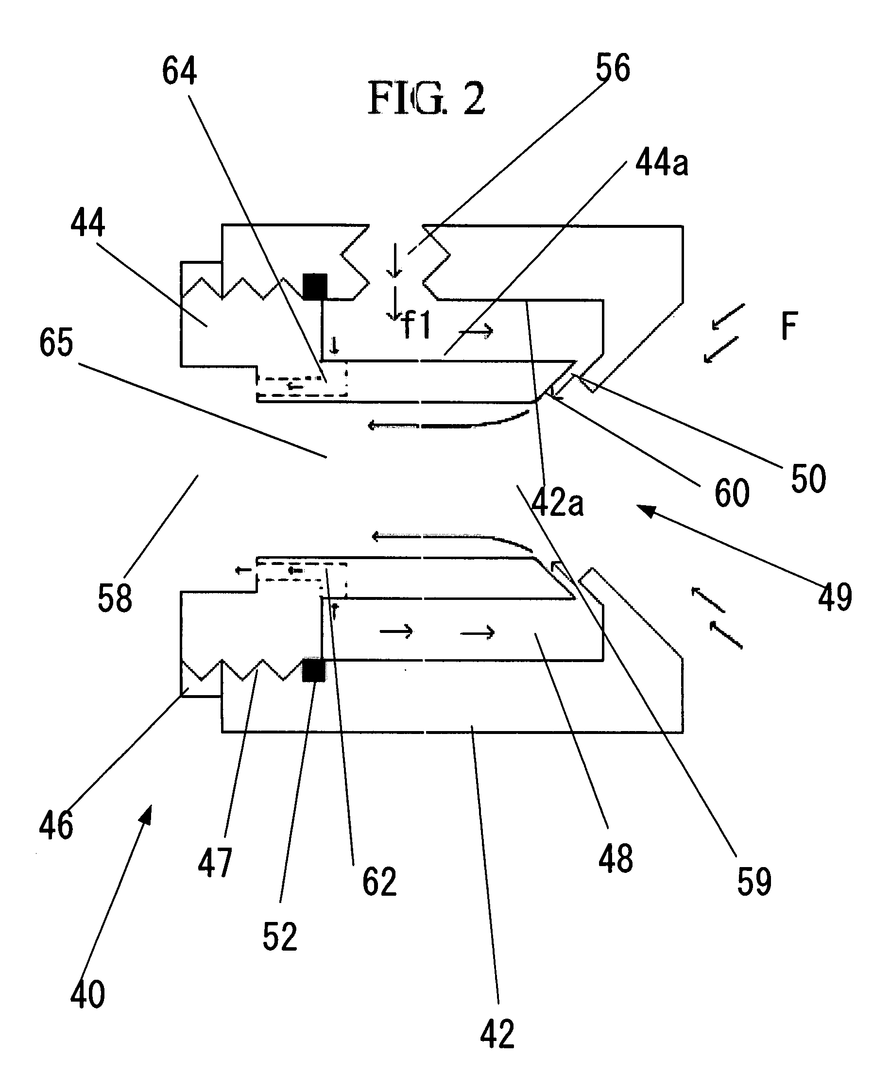
[0037]The inventors herein have developed a fluid flow amplifier that will have the ability to operate at pressures ranging from 8.5 atm (125 psig) to 68 atm (1000+ psig) without flow reversal and turbulence, as what commonly happens in current-art air amplifiers. The use of a by-pass or secondary nozzle assists the primary nozzle such that pressurized airflow discharged from the primary nozzle is forced to flow to the rear of the air amplifier as smoothly as possible. The benefit a secondary nozzle is that it allows for obtaining high energy air flows needed for a turbomachine to acquire supersonic tip speeds.

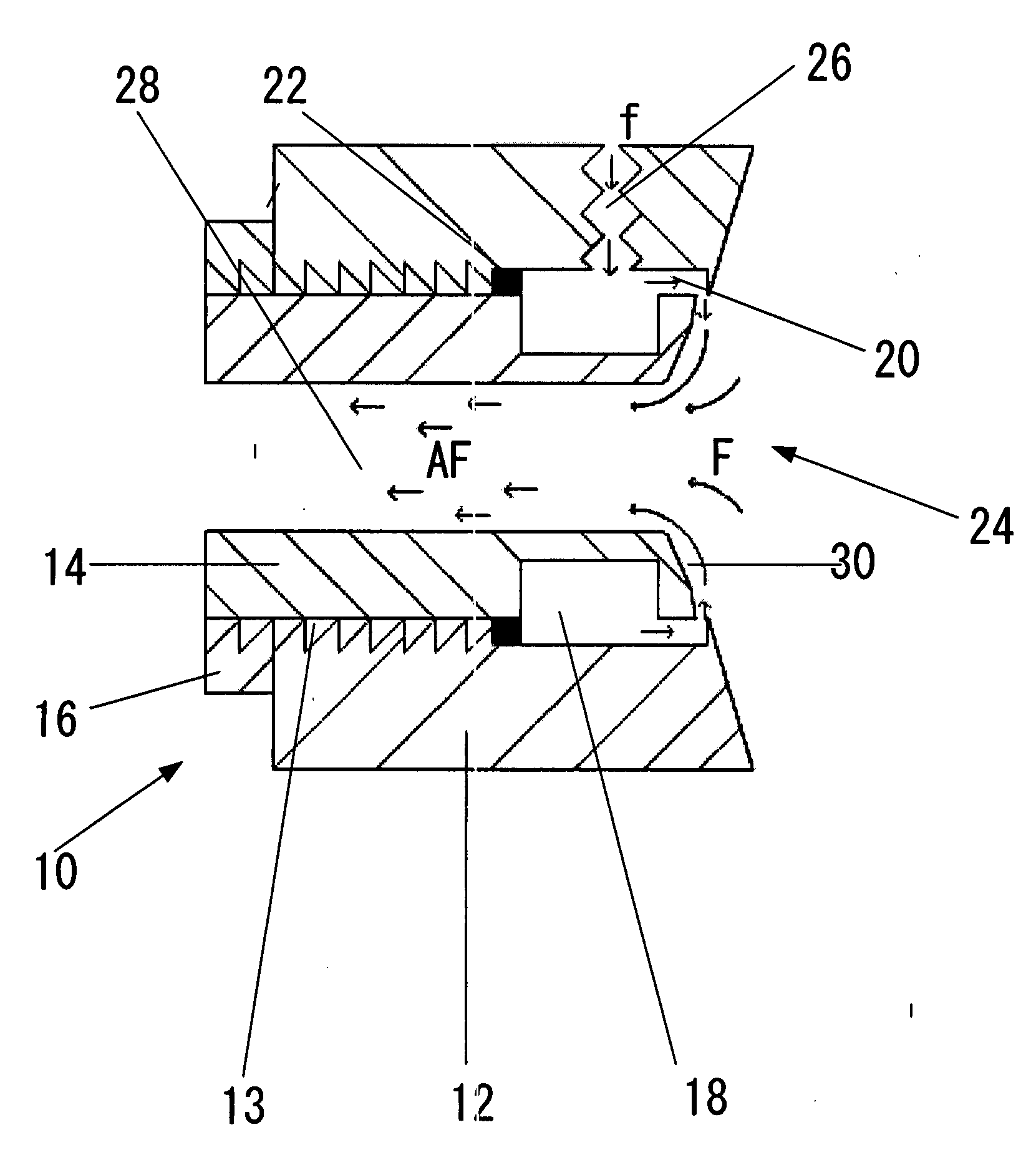
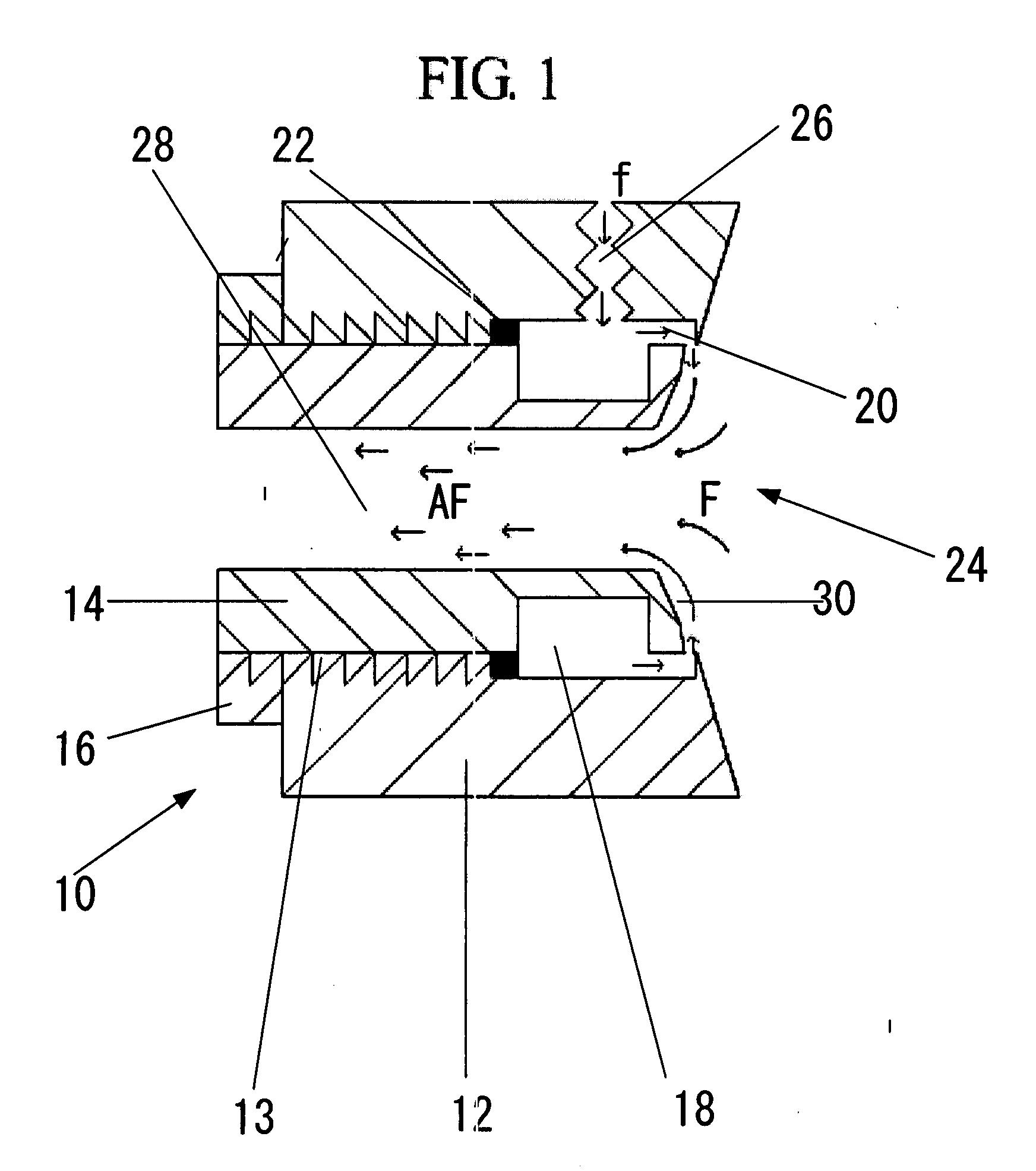
[0038]FIG. 2 is a view of an arrangement according to one embodiment of the present invention that illustrates a fluid flow amplifier with a by-pass or secondary nozzle. The arrangement shown in FIG. 2 consists essentially of an air amplifier 40 having a body 42, and a plug 44 connected to an amplifier body 42, e.g., by means of a threaded connection 47, ...


PUM


Abstract

A by-pass fluid flow amplifier which contains a primary nozzle and a primary profile for discharging compressed air into a conduit of the air amplifier and entraining ambient air in the process. A secondary nozzle and a secondary profile for discharging compressed air into the conduit of the air amplifier towards the rear that assists the primary nozzle such as to allow consistent fluid wall attachment of the compressed air and the entrained air caused by the primary nozzle and the primary profile. The secondary nozzle increases the total flow of the amplifier and prohibits the total flow from traveling towards the center of the conduit where flow reversal and turbulence are likely to occur.

Description

FIELD OF INVENTION[0001]This invention relates to the field of fluid flow amplifiers and in particular to fluid flow amplifiers that can operate at high inlet pressures ranging from 125 psig to 1000 psig+ (8.77 kg / cm2 to 70 kg / cm2) while having maximum air entrainment efficiency, maximum outlet velocity, and resistance to flow reversal and turbulence.BACKGROUND OF INVENTION—PRIOR ART[0002]Fluid flow amplifiers, which are also called thrust jets or air flow amplifiers when the fluid is air, are pressure velocity transducers that use a small amount of a compressed fluid, e.g., compressed air, as their power source. Normally, such a device consists of two pieces. The first piece is called a body and the second piece is called a plug. The plug typically has a seal ring to seal pressurized air from leaking. The plug is screwed into the body thus forming an annular chamber and a nozzle between the body and the plug. The body has an inlet to which compressed air is introduced. As compresse...

Claims


Application Information

Patent Timeline
Patent Type & Authority Applications(United States)
IPC IPC(8): F15C3/12F15C1/08
CPCF15C1/08F15C1/008Y10T137/2202Y10T137/2164Y10T137/2224
Inventor DUMAS, ELIJAHDUMAS, ELISHADUMAS, HOWARD
Owner DUMAS ELIJAH
Why Eureka
Try Eureka