
Layered low density parity check decoding for digital communications

a parity check and digital communication technology, applied in the field of digital data communications, can solve the problems of data corruption due to noise, the likelihood of data communication error must be considered, and the inability to correct every tim

Active Publication Date: 2006-11-21
TEXAS INSTR INC
View PDF17 Cites 89 Cited by
  • Summary
  • Abstract
  • Description
  • Claims
  • Application Information

AI Technical Summary

Benefits of technology

[0019]It is therefore an object of this invention to provide an LDPC decoder that can be efficiently implemented in an integrated circuit.
[0020]It is a further object of this invention to provide such an LDPC decoder in which significant efficiencies in the speed of decoding can be attained.
[0021]It is a further object of this invention to provide such an LDPC decoder in which the memory resources required for decoding can be greatly reduced relative to previous implementations.
[0022]It is a further object to provide such an LDPC decoder in which the integrated circuit area required for memory and logic resources can be greatly reduced relative to previous implementations.

Problems solved by technology

A problem that is common to all data communications technologies is the corruption of data due to noise.
In short, the likelihood of error in data communications must be considered in developing a communications technology.
Of course, this simple redundant approach does not necessarily correct every error, but greatly reduces the payload data rate.
In this example, a predictable likelihood remains that two of three bits are in error, resulting in an erroneous majority vote despite the useful data rate having been reduced to one-third.
However, high-performance LDPC code decoders are difficult to implement into hardware.
However, it has been observed that these prior approaches are somewhat limited, in that these approaches are limited to a single code or a small selection of codes.

Method used


Image

  • Layered low density parity check decoding for digital communications
  • Layered low density parity check decoding for digital communications
  • Layered low density parity check decoding for digital communications

Examples


Embodiment Construction

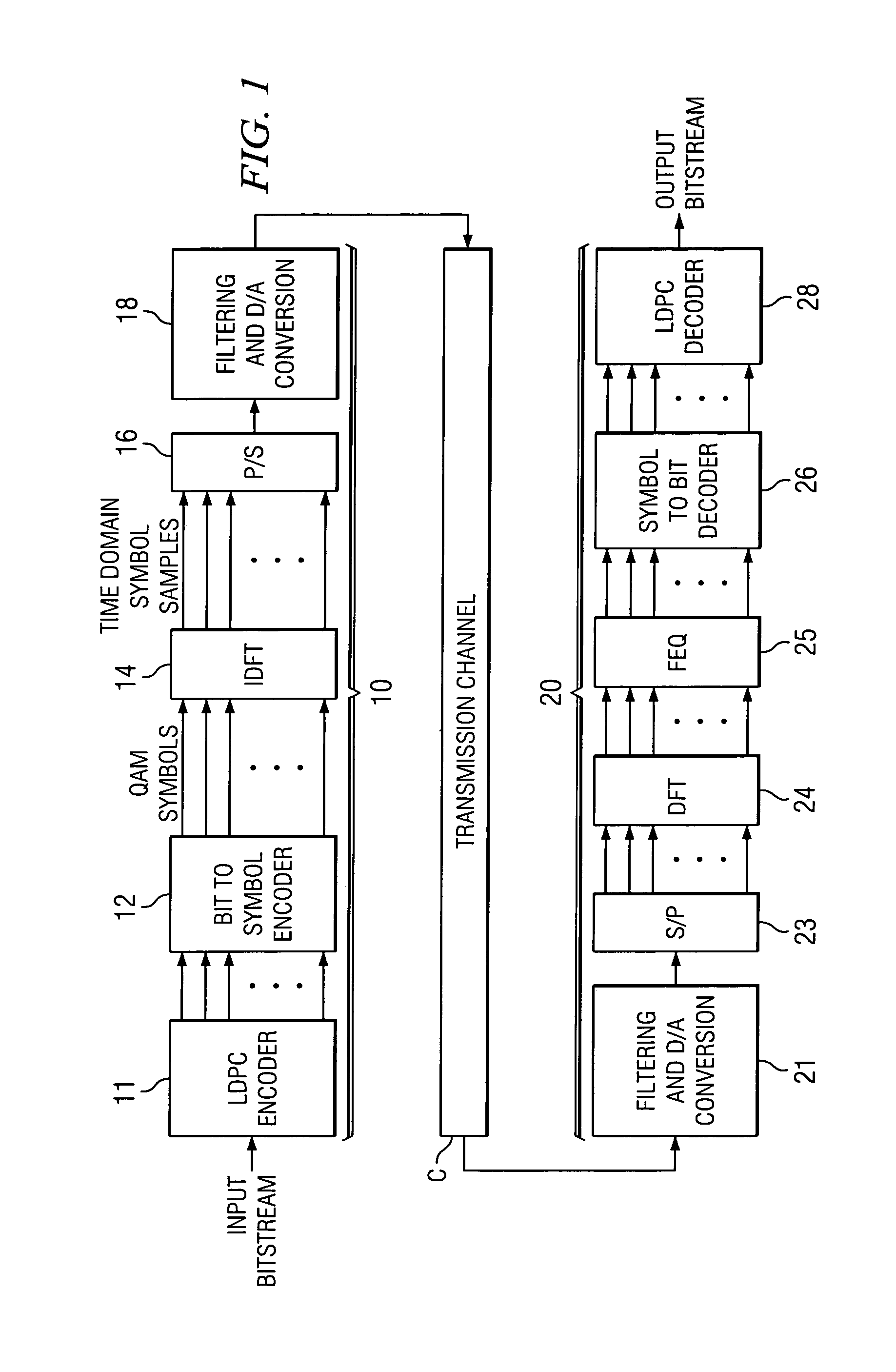
[0031]The present invention will be described in connection with an example of its implementation in an exemplary transceiver, for example a wireless network adapter such as according to the IEEE 802.11 wireless standard. It will be apparent to those skilled in the art having reference to this specification that this invention is particularly well-suited for use in such an application. However, it is also contemplated that this invention will be of similar benefit in many other applications that involve error correction coding, including communications according to orthogonal frequency division multiplexing (OFDM), discrete multitone modulation (DMT) for example as used in conventional Digital Subscriber Line (DSL) modems, and other modulation and communication approaches, whether carried out as land line or wireless communications. It is therefore to be understood that these and other alternatives to and variations on the embodiment described below are contemplated to be within the...


PUM


Abstract

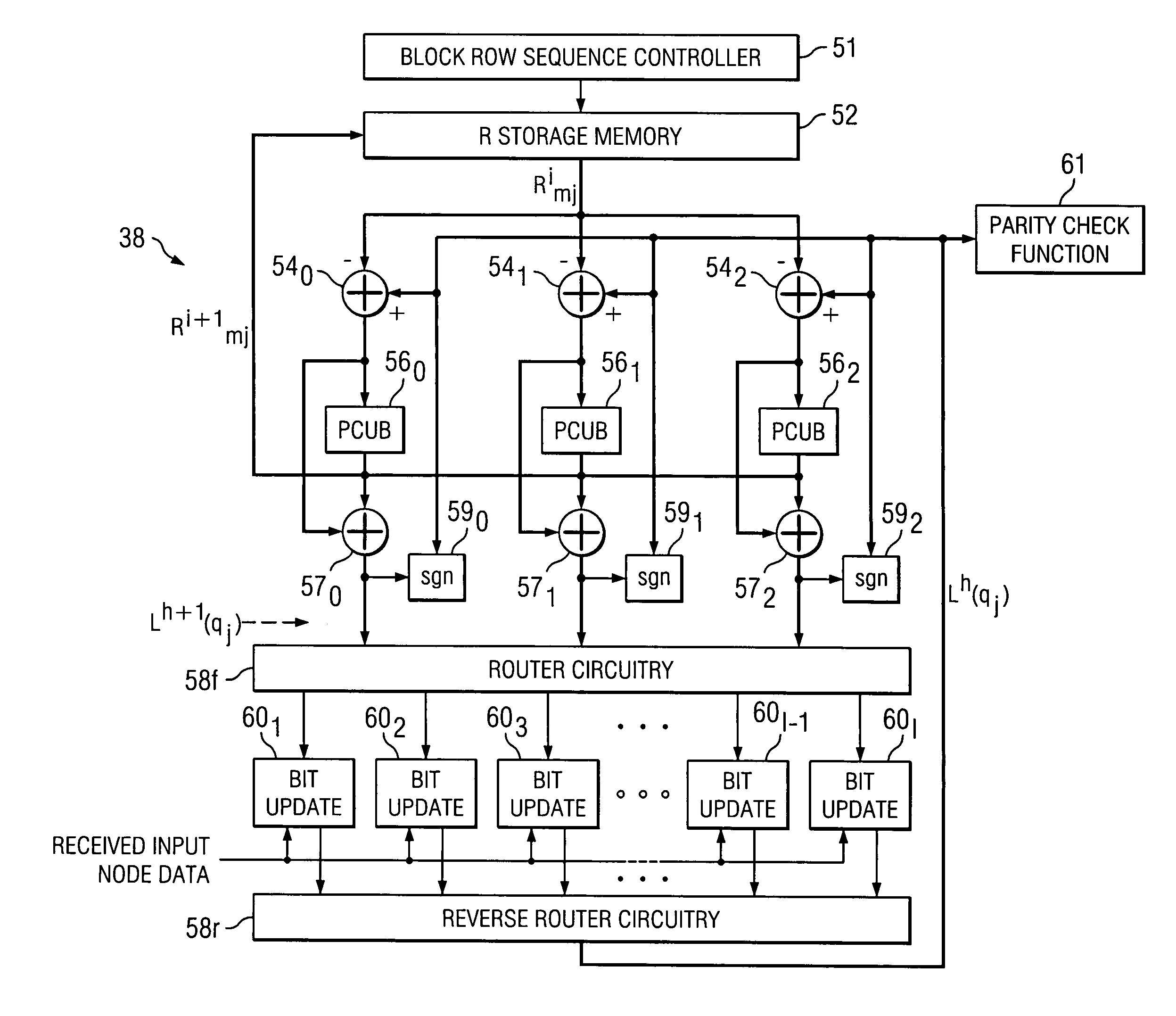
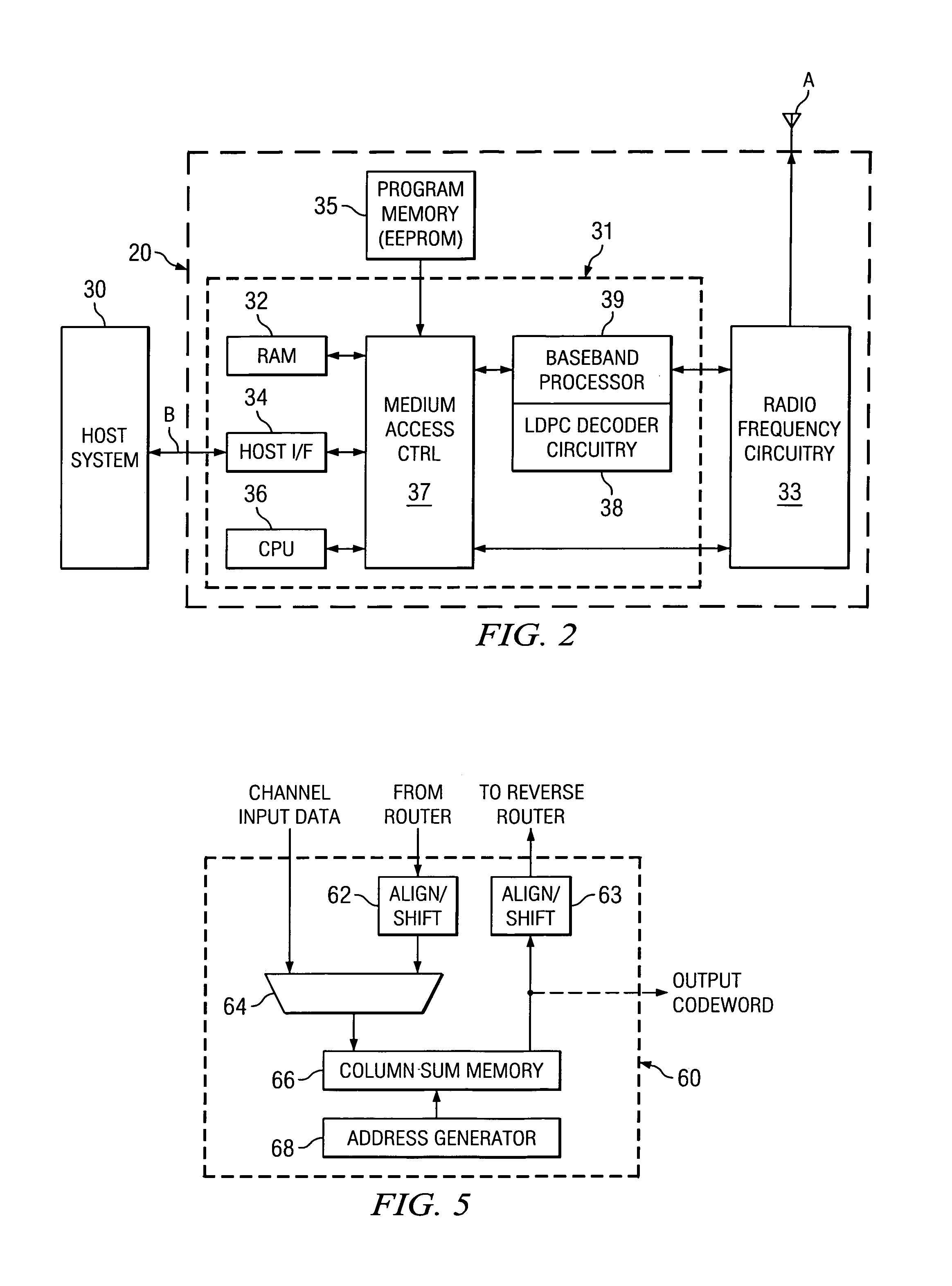
A low density parity check (LDPC) code that is particularly well adapted for hardware implementation of a belief propagation decoder circuit (38) is disclosed. The LDPC code is arranged as a parity check matrix (H) whose rows and columns represent check sums and input nodes, respectively. The parity check matrix is grouped into subsets of check sum rows, in which the column weight is a maximum of one. The decoder circuitry includes a parity check value estimate memory (52). Adders (54) generate extrinsic estimates, from immediately updated input node probability estimates, and the extrinsic estimates are applied to parity check update circuitry (56) for generating new parity check sum value estimates. These parity check sum value estimates are stored back into the memory (52), and after addition with the extrinsic estimates, are stored in a column sum memory (66) of a corresponding bit update circuit (60) as updated probability values for the input nodes.

Description

CROSS-REFERENCE TO RELATED APPLICATIONS[0001]This application claims priority, under 35 U.S.C. §119(e), of Provisional Application No. 60 / 457,003, filed Mar. 24, 2003.STATEMENT REGARDING FEDERALLY SPONSORED RESEARCH OR DEVELOPMENT[0002]Not ApplicableBACKGROUND OF THE INVENTION[0003]This invention is in the field of digital data communications, and is more specifically directed to decoding of transmissions that have been coded for error detection and correction.[0004]High-speed data communications, for example in providing high-speed Internet access, is now a widespread utility for many businesses, schools, and homes. At this stage of development, such access is provided according to an array of technologies. Data communications are carried out over existing telephone lines, with relatively slow data rates provided by voice band modems (e.g., according to the current v.92 communications standards), and at higher data rates using Digital Subscriber Line (DSL) technology. Another moder...

Claims


Application Information

Patent Timeline
Patent Type & Authority Patents(United States)
IPC IPC(8): H03M13/11H03M13/25H04L1/00
CPCH03M13/1185H03M13/255H04L1/0041H04L1/0057H03M13/1114H03M13/1134H03M13/1137H03M13/116H03M13/118
Inventor HOCEVAR, DALE E.
Owner TEXAS INSTR INC
Learn More