Communication system, communication device, program and communication control method
a communication system and control method technology, applied in the field of communication systems, can solve problems such as ineffective secondary use of spectrum, and achieve the effect of efficient secondary use of spectrum
- Summary
- Abstract
- Description
- Claims
- Application Information
AI Technical Summary
Benefits of technology
Problems solved by technology
Method used
Image
Examples
first embodiment
[3-2. First Embodiment]
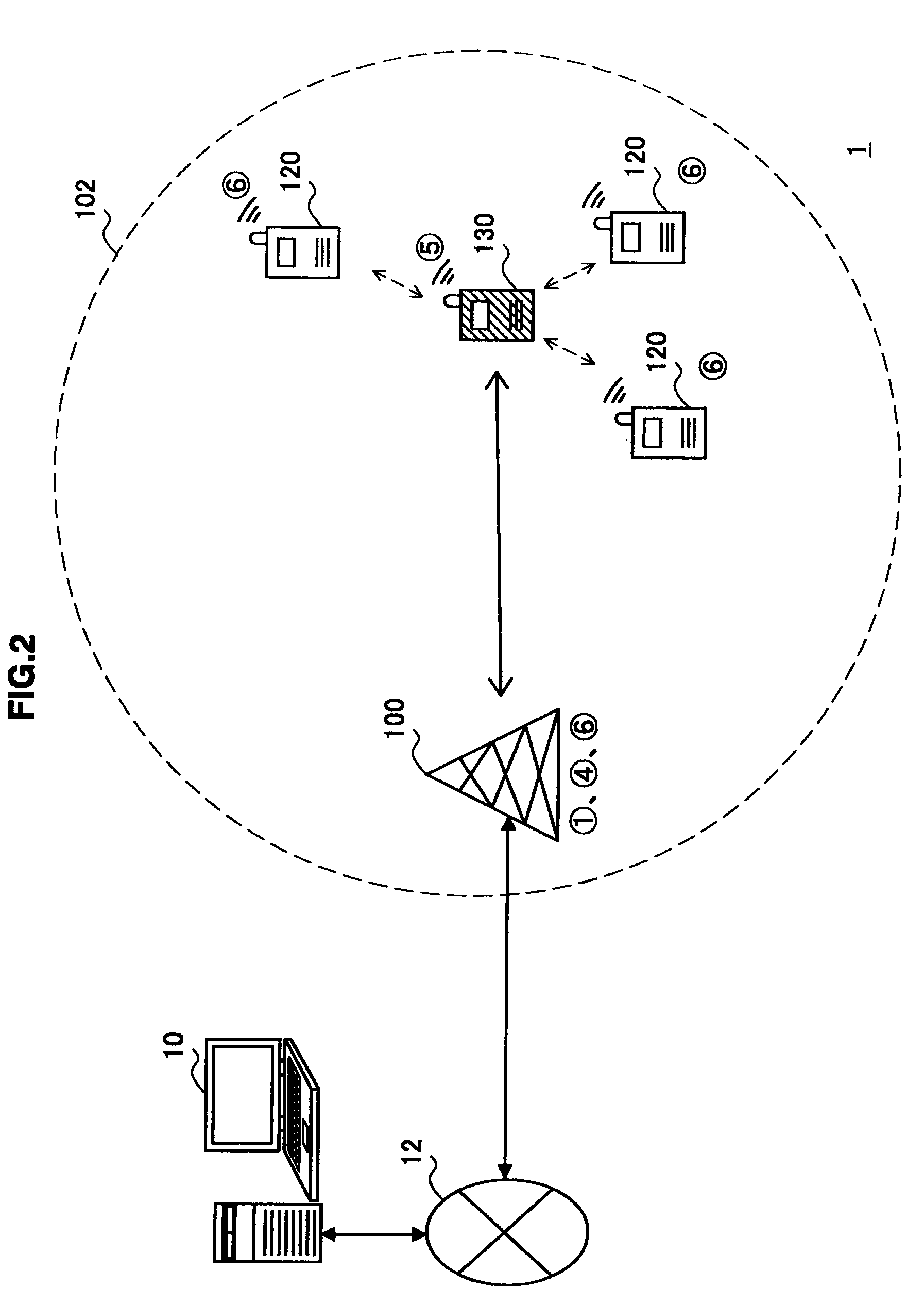
[0080]FIG. 2 is a schematic view showing an example of a configuration of a communication system 1 according to a first embodiment of the present invention. FIG. 3 is a block diagram showing an example of a functional layout among devices in the communication system 1 shown in FIG. 2.
[0081]Referring to FIG. 2, the communication system 1 includes a base station 100, three sensor devices 120 and a smart sensor device 130. The three sensor devices 120 and the smart sensor device 130 are located inside an area 102 where communication with the base station 100 is possible. The base station 100 is connected to an information processing device 10 through a network 12, which is a fixed network.
[0082]The base station 100 can provide the first communication service to the devices located inside the area 102. Further, the base station 100 coordinates secondary usage of an unused part (or whole) of the spectrum assigned to the first communication service.
[0083]To be more ...
second embodiment
[3-4. Second Embodiment]
[0092]FIG. 6 is a schematic view showing an example of a configuration of a communication system 2 according to a second embodiment of the present invention. FIG. 7 is a block diagram showing an example of a functional layout among devices in the communication system 2 shown in FIG. 6.
[0093]Referring to FIG. 6, the communication system 2 includes a base station 200, two sensor devices 220, two sensor devices 222, a smart sensor device 230, and a determination device 240. The two sensor devices 220, the smart sensor device 230 and the determination device 240 are located inside an area 202 where communication with the base station 200 is possible. The base station 200 is connected to an information processing device 10 through a network 12, which is a fixed network.
[0094]The base station 200 can provide the first communication service to the devices located inside the area 202. Further, the base station 200 (or the information processing device 10) can tempora...
third embodiment
[3-5. Third Embodiment]
[0101]FIG. 8 is a schematic view showing an example of a configuration of a communication system 3 according to a third embodiment of the present invention. FIG. 9 is a block diagram showing an example of a functional layout among devices in the communication system 3 shown in FIG. 8.
[0102]Referring to FIG. 8, the communication system 3 includes a base station 300, two sensor devices 320, two sensor devices 322, a smart sensor device 330, and a determination device 350. The two sensor devices 320, the smart sensor device 330 and the determination device 350 are located inside an area 302 where communication with the base station 300 is possible. The base station 300 is connected to an information processing device 10 through a network 12, which is a fixed network.
[0103]The base station 300 can provide the first communication service to the devices located inside the area 302.
[0104]On the other hand, the sensor devices 320 and the sensor devices 322 operate as ...
PUM
 Abstract
Description
Claims
Application Information
 - R&D
- Intellectual Property
- Life Sciences
- Materials
- Tech Scout
- Unparalleled Data Quality
- Higher Quality Content
- 60% Fewer Hallucinations
Browse by: Latest US Patents, China's latest patents, Technical Efficacy Thesaurus, Application Domain, Technology Topic, Popular Technical Reports.
© 2025 PatSnap. All rights reserved.Legal|Privacy policy|Modern Slavery Act Transparency Statement|Sitemap|About US| Contact US: help@patsnap.com


