
System and method of predictive occupancy room conditioning

a technology for predicating occupancy and room conditioning, applied in the direction of program control, heating types, instruments, etc., can solve the problems of energystar thermostats not performing [energystar], and achieve the effect of reducing energy used in areas, maximum comfort and efficiency, and reducing energy consumption

Inactive Publication Date: 2012-03-22
MOUNTAINLOGIC
View PDF15 Cites 89 Cited by
  • Summary
  • Abstract
  • Description
  • Claims
  • Application Information

AI Technical Summary

Benefits of technology

"The patent describes a new system for controlling the temperature in a home using sensors and a learning software program. The system predicts when a person will need to use the air conditioning or heating and adjusts the temperature accordingly. This saves energy by reducing the amount of unused energy in the home. The system is easy to install and use, and can be integrated with other energy efficiency measures. The system is cost-effective and has a high level of user acceptance and comfort. The technical effects of the patent are a more efficient and cost-effective way to control the temperature in a home, reducing energy waste and greenhouse emissions."

Problems solved by technology

Existing programmable EnergyStar thermostats' failure to perform [EnergyStar] in the field as well as anticipated is largely due to their complex user interface.

Method used

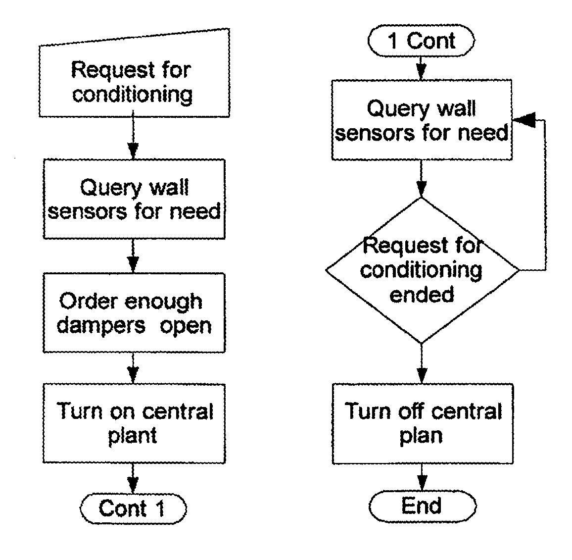
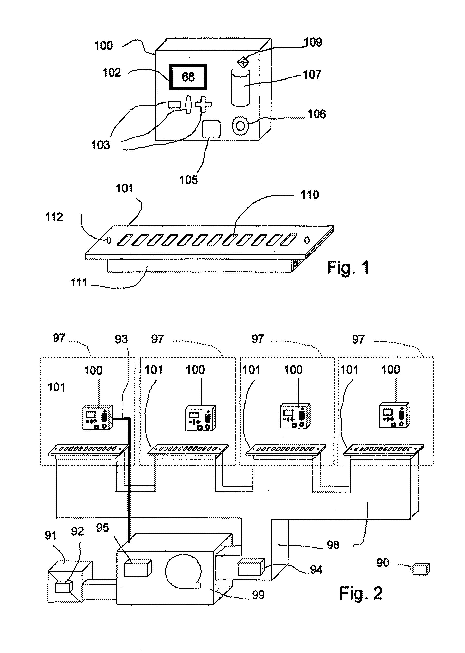
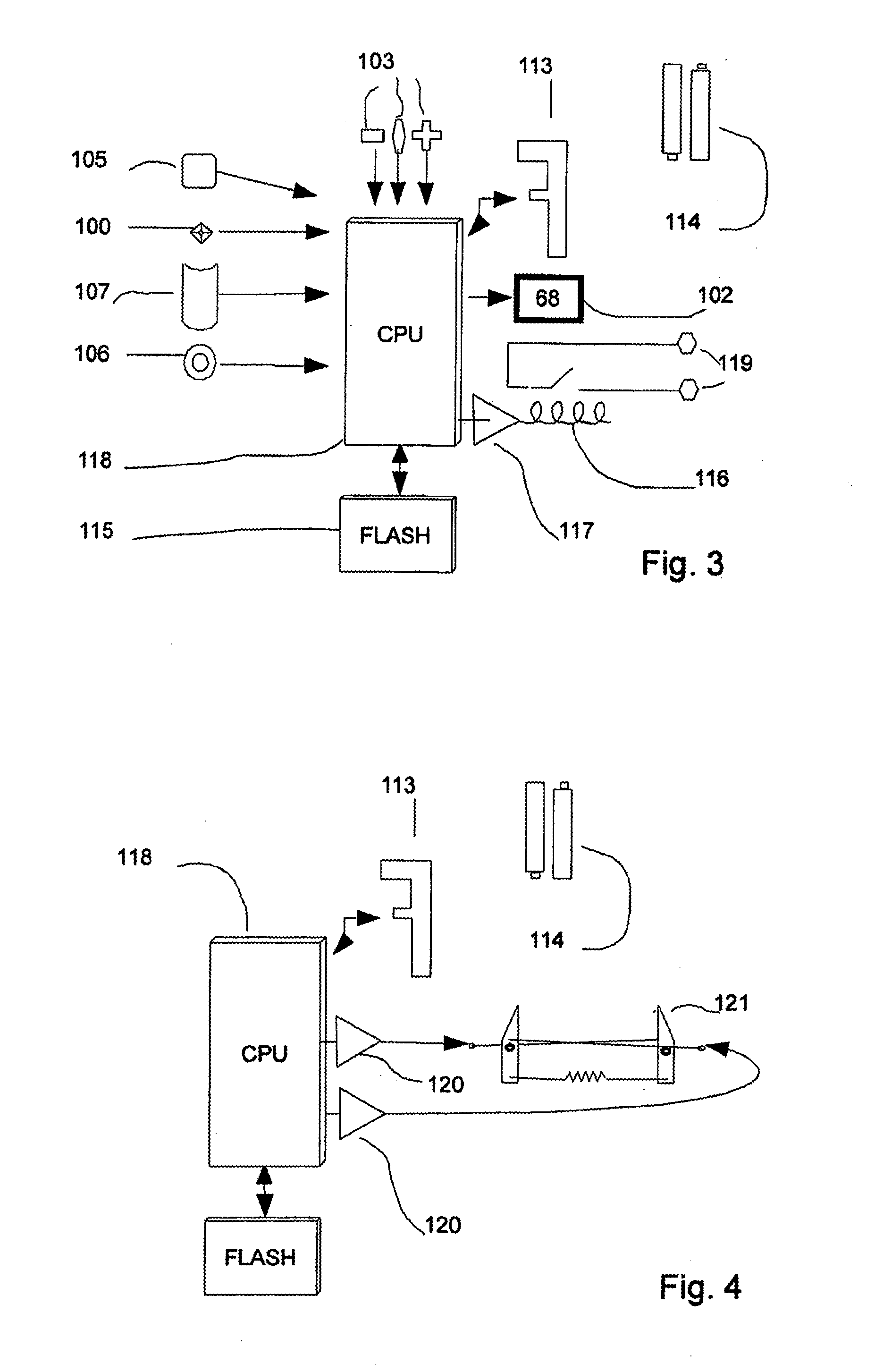

Image

  • System and method of predictive occupancy room conditioning
  • System and method of predictive occupancy room conditioning
  • System and method of predictive occupancy room conditioning

Examples


Embodiment Construction

[0050]In the following description, for purposes of explanation and non-limitation, specific details are set forth, such as particular nodes, functional entities, techniques, protocols, standards, etc. in order to provide an understanding of the described technology. It will be apparent to one skilled in the art that other embodiments may be practiced apart from the specific details disclosed below. In other instances, detailed descriptions of well-known methods, devices, techniques, etc. are omitted so as not to obscure the description with unnecessary detail. Individual function blocks are shown in the figures. Those skilled in the art will appreciate that the functions of those blocks may be implemented using individual hardware circuits, using software programs and data in conjunction with a suitably programmed microprocessor or general purpose computer, using applications specific integrated circuitry (ASIC), and / or using one or more digital signal processors (DSPs). Generally ...


PUM


Abstract

A HVAC controls system for zone controls that is comprised of one or more Wall Sensor Units (WSU) and zero or more Damper / Register Units (DRUs). The invention is a low networked cost solution for residential and light commercial that is easy to install in new and existing building. The WSUs detect, log and use occupancy data to predict where in a building HVAC conditioning is needed and to save energy where it is not needed. The DRU use shape memory alloy wires to control the opening and closing of a damper plate with very little power allowing batter operation.

Description

CROSS-REFERENCE TO RELATED APPLICATION[0001]This application is a continuation of U.S. patent application Ser. No. 12 / 284,795, filed Sep. 25, 2008, now pending, which application claims the benefit of U.S. Provisional Application No. 60 / 997,426, filed on Oct. 4, 2007, which application is incorporated herein by reference in its entirety.BACKGROUND OF THE INVENTION[0002]The technical field of this invention relates to zoned residential Heating Ventilation and Air Conditioning (HVAC) and lighting controls that employ embedded systems and wireless communications. HVAC systems use a large proportion of a building's energy usage and need to be optimized for both environmental and economic reasons.[0003]There is a long history of invention and research associated with HVAC technology. Programmable Thermostats: Programmable setback thermostats that can be set by the occupant for set point, reset point and schedule have been available on the market for a number of years [EnergyStar]. In spi...

Claims


Application Information

Patent Timeline
Patent Type & Authority Applications(United States)
IPC IPC(8): G05D23/00
CPCF24F11/0009F24F11/0012F24F11/0034G05D23/1934G05B15/02G05B2219/2642G05D23/1921F24F11/0076F24F11/30F24F2110/10F24F2120/10F24F11/70F24F11/52F24F11/58F24F11/46F24F11/63
Inventor ELLIOTT, SCOTT
Owner MOUNTAINLOGIC
Learn More