Electromagnetic apparatus and method for controlling fluid flow

a technology of electromagnetic apparatus and fluid flow, applied in the direction of diaphragm valve, valve details, valve arrangement, etc., can solve the problems of metal problems, reduce the longevity of batteries, and damage to armatures, so as to reduce energy consumption, reduce energy waste, and reduce energy consumption. effect of large amoun

Inactive Publication Date: 2007-10-18
SLOAN VALVE COMPANY
View PDF99 Cites 58 Cited by
  • Summary
  • Abstract
  • Description
  • Claims
  • Application Information

AI Technical Summary

Benefits of technology

[0019] This use of the armature sensor reduces the energy waste that usually occurs in driving the actuator's armature. An armature sensor may monitor the armature movement or determine when the armature has reached the end of its travel. At a selected point, based on the signal from the armature sensor, a drive signal to the actuator coil drive ends. This can reduce energy consumption greatly, because coil-drive duration does not always need to be long enough to meet worst-case requirements, which are usually applied to assure opening or closing when there is no armature sensor. This reduction of energy use results in a significant battery-longevity increase. Further, a sensor can check if the actuator is functioning properly, and aid in monitoring the condition of the actuator in question. These measurements show the state of the condition of the valve. Once the armature reaches the end position and makes a sound, for example, the sensor generates a sensor output indicative of the sound sensed. The sound sensor may be such as described in U.S. Pat. Nos. 6,450,478; 6,305,662; 6,293,516, which are incorporated by reference. Other signals indicative of the armature position may be used.
[0020] Advantageously, the use of the membrane enables the use of armature materials with a high magnetic permeability such as the ferromagnetic types of carbon steel or stainless steel regardless of their low corrosion resistance, and the armature does not need to be subjected to a number of treatment steps to afford an acceptable level of corrosion resistance. Furthermore, the present design reduces the solenoid-wire size currently required because of a regular armature's non-optimal magnetic permeability. When the actuator includes a flexible membrane secured over the end of the pocket in which the armature travels, the armature's high-permeability material is not exposed to the possibly corrosive fluid whose flow the valve is to control. The armature pocket is filled with an incompressible fluid so as to counterbalance the force exerted by the controlled fluid's pressure. The flexible membrane also protects the valve assembly from contaminants present in the fluids flowing in and controlled by the valve assembly.

Problems solved by technology

In non-latching actuators, unnecessarily high drive current for holding the valve open also may needlessly reduce the battery's longevity.
This usually causes degradation of the armature (i.e., corrosion) and problems with metal and other ions (or other deposits) that accumulate within the bobbin's cavity.
However, materials with very high magnetic permeability usually have low corrosion resistance.
Thus, designers in the past have had to compromise permeability for corrosion resistance.
For example, carbon steel has a high magnetic permeability, but is quite vulnerable to rust and corrosion.
Still, designers have had problems with the above-described deposits, or conversely, problems with preventing fluid contamination of the armature, bobbin or other valve elements.

Method used


Image

  • Electromagnetic apparatus and method for controlling fluid flow
  • Electromagnetic apparatus and method for controlling fluid flow
  • Electromagnetic apparatus and method for controlling fluid flow

Examples


Embodiment Construction

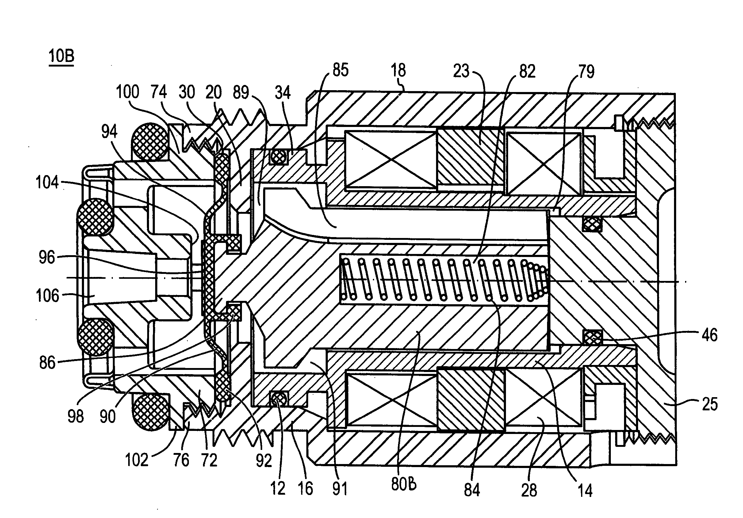
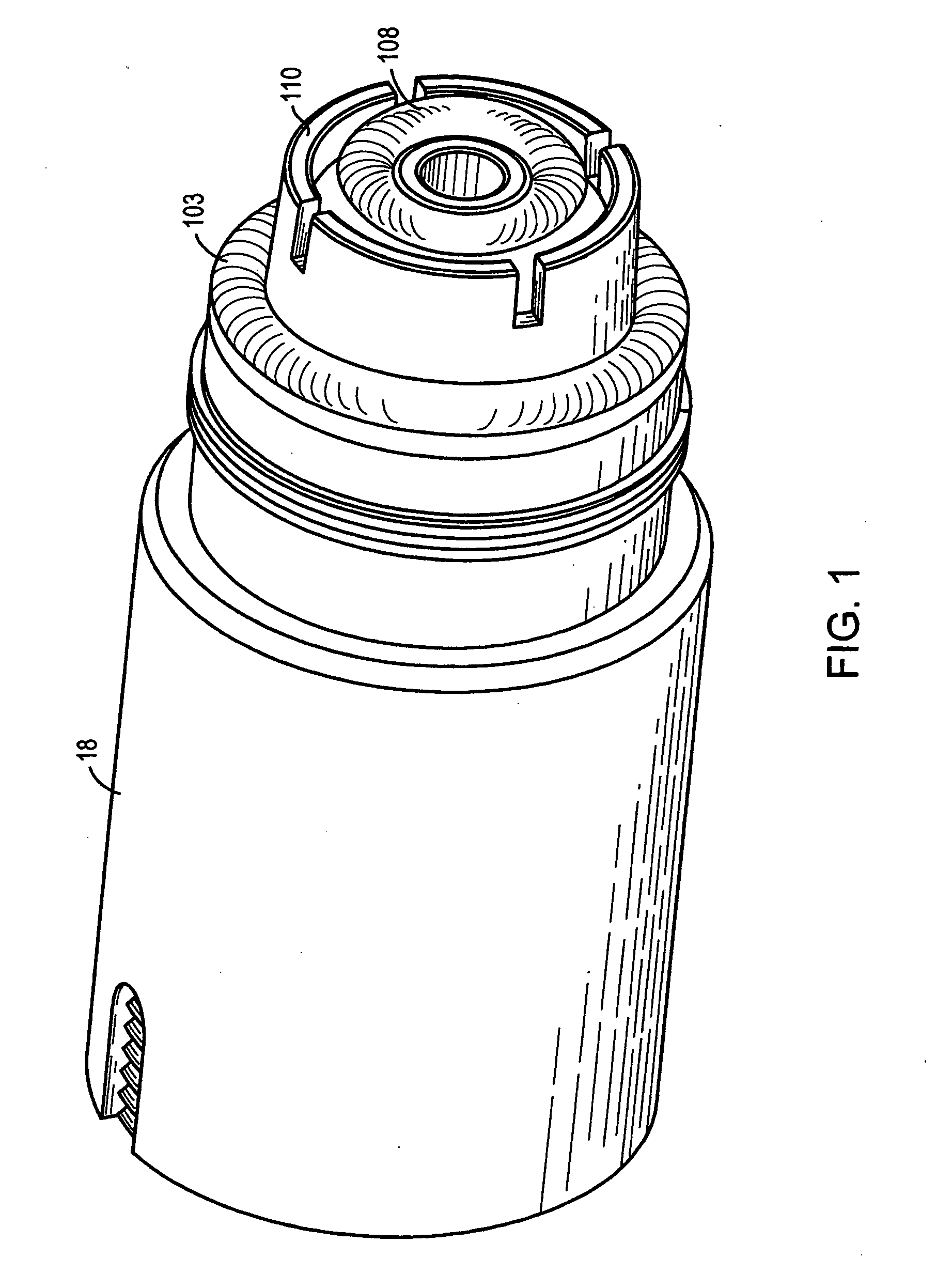
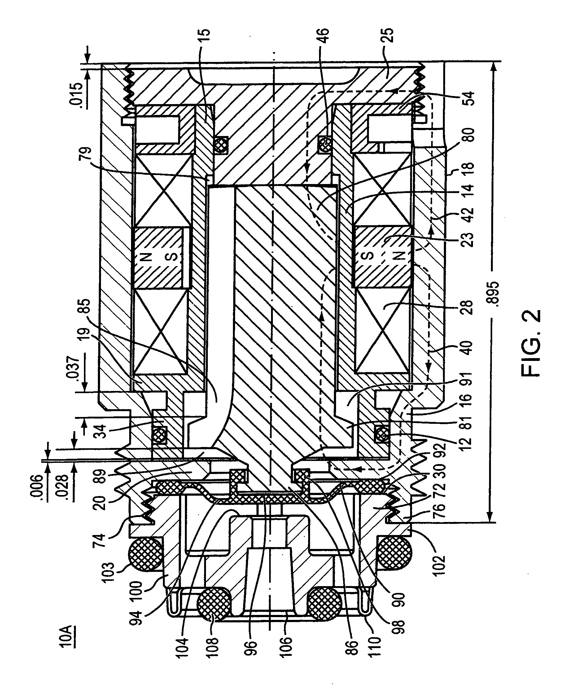
[0034] Industrial, agricultural and household systems use various types of valves that use electromagnetic actuators for controlling fluid flow. Referring to FIG. 1, an electrically operable valve 10A uses force from magnetic fields and the biasing force of a radial magnet to drive an armature within an actuator into a valve seat, thereby stopping flow through a conduit, and to move the armature away from the valve seat, thereby opening the valve once more.

[0035]FIGS. 1 and 2 illustrate an embodiment of the electrically operable valve 10A. As seen in FIG. 2, the valve actuator 10A includes an annular magnet 23, a rear pole piece 25, a ferromagnetic armature 80, and the solenoid windings 28 wound about a solenoid bobbin 14. The valve also includes a resilient membrane 90 and a replaceable pilot body member 100, which defines the valve geometry. Resilient membrane 90 includes a thickened peripheral rim 92, flexible portion 94, portion 98, surrounding the plunger tip, and deformable s...


PUM


Abstract

An actuator including actuator base, bobbin, and pole piece forming a pocket for a ferromagnetid armature located therein. The actuator including a radial magnet and a solenoid coil constructed and arranged to cause a linear displacement of the armature upon application of a coil drive current from a control circuit. The actuator may include a flexible membrane that partially encloses the armature to form an armature chamber filled with an incompressible fluid. In a valve design, a fluid flow is stopped by driving the membrane against a valve seat. Pressure from the controlled fluid in the conduit is transmitted through the membrane to the fluid within the armature chamber so that the armature does not need to counteract force applied to the membrane by the conduit fluid's pressure. A fluid flow is opened by driving the membrane away from the valve seat.

Description

[0001] This application also claims priority from U.S. provisional Application 60 / 659,343 filed on Mar. 5, 2005. This application is also a continuation-in-part of U.S. application Ser. No. 10 / 421,359, filed on Apr. 23, 2003, entitled “Apparatus and Method for Controlling Fluid Flow,” which is a continuation of PCT Application PCT / US01 / 51098, filed on Oct. 25, 2001, which is continuation-in-part of U.S. application Ser. No. 09 / 696,154, filed on Oct. 25, 2000, now U.S. Pat. No. 6,609,698. This application is also a continuation-in-part of U.S. application Ser. No. 10 / 610,954, filed on Jul. 1, 2003, which is a continuation of U.S. application Ser. No. 10 / 037,473, filed on Oct. 19, 2001, which is a continuation of U.S. application Ser. No. 09 / 514,491, filed on Feb. 29, 2000, now U.S. Pat. No. 6,305,662, is a continuation-in-part of U.S. application Ser. No. 09 / 924,130, filed on Aug. 7, 2001, now U.S. Pat. No. 6,450,478. The disclosure of all of the above-mentioned applications is consi...

Claims


Application Information

Patent Timeline
Patent Type & Authority Applications(United States)
IPC IPC(8): F16K31/02
CPCF16K7/16F16K31/0655F16K31/0672F16K37/0041F16K31/082F16K37/00F16K41/12F16K31/0675
Inventor HERBERT, KAYPARSONS, NATAN E.MO, XIAOXIONGGULER, FATIH
Owner SLOAN VALVE COMPANY
Why Eureka
Try Eureka