Aircraft Fuselage Heating

a technology for fuselage shells and aircraft, which is applied to aircraft accessories, aircraft floors, air-treatment apparatus arrangements, etc., can solve the problems of increasing fuel consumption, affecting the service life of aircraft, and not being practical for many passenger and transport aircraft, so as to prevent ice formation and prevent ice formation. , the temperature of the aircraft fuselage shell structure is increased, and the effect of preventing ice formation

Inactive Publication Date: 2008-12-11
CALAMVOKIS HAL ERRIKOS
View PDF3 Cites 28 Cited by
  • Summary
  • Abstract
  • Description
  • Claims
  • Application Information

AI Technical Summary

Benefits of technology

[0012]wherein the heater is adapted to drive moisture from air in a region disposed immediately adjacent the structure to air in a region disposed from the structure within the enclosed space, thereby substantially preventing ice formation on the interior of the structure when the exterior of the structure is exposed to temperatures in the region of −35° C. to −85° C.
[0013]According to a second aspect of the invention, a method of heating an aircraft fuselage comprises the step of supplying heat energy to air occupying an interior space enclosed by an aircraft fuselage shell structure so as to drive moisture from air in a region disposed immediately adjacent the structure to air in a region disposed from the structure within the enclosed space, thereby substantially preventing ice formation on the interior of the structure when the exterior of the structure is exposed to temperatures in the region of −35° C. to −85° C.
[0014]The aircraft fuselage of the first aspect and the method of the second aspect of the invention advantageously solve the above-mentioned problems of the prior art. The humidity of the air in the region disposed immediately adjacent the fuselage shell structure is made lower than that in the region disposed from the structure within the enclosed space. The temperature of the aircraft fuselage shell structure is increased by the heat supplied. These combined effects ensure not only that the rate of condensation of moisture from the air on the interior side of the aircraft fuselage shell structure is reduced but also that any condensation that does form has a reduced possibility of freezing. Substantial prevention of ice formation on the interior side of the aircraft fuselage shell structure provides reduced fuel burn for the aircraft in cruise flight and reduced corrosion and damage to the fuselage shell structure. The air occupying the enclosed space is simultaneously heated.
[0015]The present invention may reduce the amount of fuselage insulation required thus potentially providing an overall weight loss for the aircraft delivering operational advantages and cost savings.
[0016]Also, by driving moisture into the region of air disposed from the fuselage shell structure passengers in the cabin of passenger aircraft may have an improved flight experience due to the greater humidity of the cabin air.
[0017]Furthermore, by increasing the temperature of the aircraft fuselage shell structure the invention has the advantage of significantly reducing the occasions when the aircraft fuselage shell structure requires the application of de-icing fluid to its exterior side when the aircraft is on the ground during winter operations. This has a significant bearing on environmental impact of aircraft due to reduced chemical and energy waste, reduced preparation time of aircraft for winter operations, providing reduced operational costs overall.

Problems solved by technology

A disadvantage of flying at these high altitudes is that the aircraft is often exposed to freezing temperatures of up to around −85° C. Some form of insulation and heating is therefore needed for human beings to survive at these temperatures.
This solution is not practical for many passenger and transport aircraft.
One potential problem with bleed air is that it can be extracted from the engine compressor stage at temperatures up to 300° C., which is ideal for another use of bleed air in wing and nacelle anti-icing but this may require bleed air to be cooled before its introduction to the cabin after it has been pressurised up to the required cabin air pressure.
Firstly, conventional methods of providing air at the required temperature to the cabin (either through bleed air or via electrical or hydraulic heating systems) impose a fuel burn penalty on the aircraft engines, increasing fuel consumption.
Secondly, the heated cabin air can often penetrate around, or through, the insulation blankets, particularly when the cabin air is pressurized.
Such freezing and thawing can promote corrosion of the fuselage shell structure if constructed of aluminium, or crack penetration of any microscopic imperfections in the shell structure if constructed of composite materials.
In addition, the shell structure (including any fixing brackets for cabin items) may be such that heat paths exist to the cabin side of the insulation blankets from the aerodynamic surface such that exposed portions of the shell structure on the cabin side of the insulation blanket may also reach sub-zero temperatures.
In this case, moisture in the cabin air can readily contact the exposed portions of the shell structure and freeze thereupon.
In addition, even if the cabin air is effectively prevented for coming into contact with cold or freezing parts of the shell structure, since the insulation blankets are generally in contact with the shell structure, moisture in the cabin air may condense on an interior surface of the insulation blankets due to local thermal gradient.
Not only may the weight of the ice, or trapped water, be carried onboard the aircraft for the remainder of the flight, thus imposing a weight and therefore a fuel penalty, but the lack of moisture in the cabin air may cause discomfort to any passengers.
In addition, as the aircraft descends from cruising altitude any ice will melt as the ambient temperature increases, causing potential corrosion issues for any exposed metallic surfaces of the fuselage shell structure.

Method used


Image

  • Aircraft Fuselage Heating
  • Aircraft Fuselage Heating
  • Aircraft Fuselage Heating

Examples


first embodiment

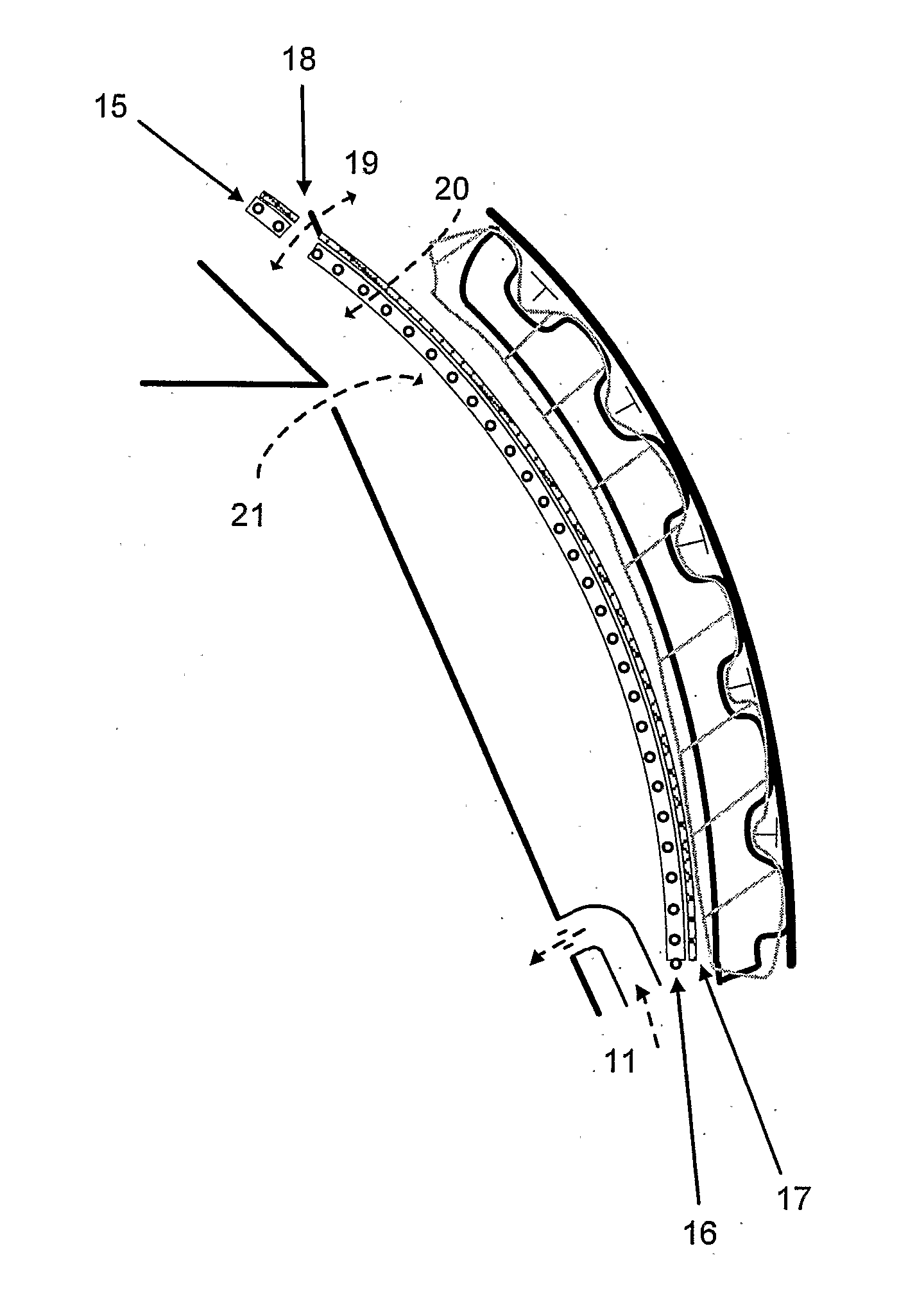
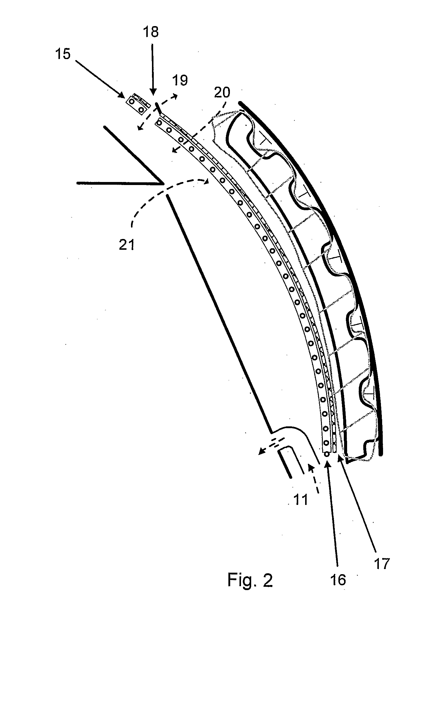
[0033]the invention will now be described with reference to FIG. 2. The aircraft fuselage shell has a similar structure to that of FIG. 1. In addition, a support layer 15 is provided carrying a heating element 16, the support layer 15 being disposed adjacent the insulation material 6 on an interior side of the fuselage shell structure. In this context, “adjacent” means “immediately adjacent” or “near to”. The support layer 15, or an additional layer placed on the fuselage side thereof, is impermeable to water droplets but is permeable to water vapour. Such a construction allows any moisture which is on the fuselage side of the support layer 15 and which condenses on an outer surface of the support layer 15, that is, on the cold side, to wick through the support layer 15 to the warm cabin side of the layer 15. To encourage this effect, the support layer 15 may be provided with a moisture absorbent insulation layer 17 on the fuselage side of the support layer 15. The insulation layer ...

second embodiment

[0039]the invention will now be described with reference to FIG. 3. The aircraft fuselage shell has a similar structure to that of FIG. 1. In addition, a pipe 22 is mounted adjacent the fuselage shell structure. In this context, “adjacent” means “immediately adjacent” or “near to”. Air is directed through openings 23 in pipe 22. Ambient air taken from outside the aircraft engines and heated by the engines through heat exchangers using the “hot end” of the engines as a heat source is pressurised and then passed through pipe 22 as indicated by arrow 24. Upon exiting the pipe 22 through openings 23 the heated air is passed over the interior side of the fuselage shell structure, as indicated by arrows 25. The air can be hotter than the desired cabin air temperature as it will heat the fuselage shell structure before dissipating throughout the cabin. The heated fuselage shell structure will then dissipate heat to the ambient airflow through surface 2. The effect of passing air over the f...


PUM


Abstract

A method of heating an aircraft fuselage comprises the step of supplying heat energy to air occupying an interior space enclosed by an aircraft fuselage shell structure so as to drive moisture from air in a region disposed immediately adjacent the structure to air in a region disposed from the structure within the enclosed space (20), thereby substantially preventing ice formation on the interior of the structure when the exterior of the structure is exposed to temperatures in the region of −35° C. to −85° C. The heat energy may be supplied by either a heater mat or a heat pipe assembly (16) in an aircraft fuselage.

Description

FIELD OF THE INVENTION [0001]The present invention relates to a method of heating a passenger or transport aircraft fuselage, devices therefor and an aircraft fuselage so heated.BACKGROUND TO THE INVENTION [0002]Commercial passenger and transport aircraft having jet engines as their propulsion system typically cruise at an altitude of around 11,000 m. At these high altitudes jet engines are particularly efficient, the aerodynamic drag penalty on the aircraft is significantly reduced when compared with cruising at lower altitude, and the aircraft is less susceptible to weather considerations. Accordingly, aircraft cruising at such high altitudes may do so efficiently and in a shorter overall trip time.[0003]A disadvantage of flying at these high altitudes is that the aircraft is often exposed to freezing temperatures of up to around −85° C. Some form of insulation and heating is therefore needed for human beings to survive at these temperatures. A solution often used in military jet ...

Claims


Application Information

Patent Timeline
Patent Type & Authority Applications(United States)
IPC IPC(8): B64D13/08
CPCB64C1/067B64D13/00B64D15/12Y02T50/44Y02T50/46Y02T50/56Y02T50/50Y02T50/40B64C1/00B64D13/06B64D15/04H05B3/36
Inventor CALAMVOKIS, HAL ERRIKOS
Owner CALAMVOKIS HAL ERRIKOS
Why Eureka
Try Eureka