Method and system for dehumidification and refrigerant pressure control

a technology of refrigerant pressure and dehumidification, which is applied in the field of heating, ventilation and air conditioner systems, can solve the problems of overcooling, overcooling is a particular problem, and overcooling is a common term, so as to reduce the system pressure, control the head pressure, and avoid the icing of the system components

Inactive Publication Date: 2006-12-28
YORK INT CORP
View PDF99 Cites 64 Cited by
  • Summary
  • Abstract
  • Description
  • Claims
  • Application Information

AI Technical Summary

Benefits of technology

[0014] Another advantage of the present invention is that the air conditioning or heat pump unit can operate at lower outdoor ambient temperatures by providing an increase in system pressure to avoid icing of the system components.
[0015] Another advantage of the present invention is that the system and method distributes refrigerant substantially uniformly across the evaporator to provide substantially uniform refrigerant phase distribution and heat exchange across the evaporator.
[0016] Another advantage of the present invention is that the system can reheat air and control head pressure without the need for a separate airflow system.
[0017] Another advantage of the system is that the simultaneous control of the head pressure of the system and reheating of the air during dehumidification permits the system to be operated in a manner that increases the efficiency and reliability of the system, while maintaining greater control of the temperature and humidity of the conditioned air.

Problems solved by technology

One drawback to using just an evaporator for dehumidification is an excess reduction in air temperature that results, which is commonly referred to as overcooling.
Overcooling is a particular problem when dehumidification is required in a room that is already relatively cool and does not require additional cooling.
The reheat coil system for providing heat to the dehumidified, overcooled air has several drawbacks including the requirement of additional equipment and / or piping and / or additional energy input.
One drawback of the '133 patent system is that the dehumidified air is not reheated and may be overcooled.
Another drawback of the '133 patent system is that the inlet header does not distribute flow across the circuits of the evaporator, leading to uneven phase distribution of refrigerant across the evaporator heat exchanger.
Another drawback of the '133 patent system is that it is nearly impossible for a properly functioning system to deliver supply air that has not been sensibly cooled.
The decrease in head pressure results in a lowering of the temperature of the refrigerant at the evaporator.
When the temperature of the refrigerant at the evaporator becomes too low, icing of the evaporator can occur.
The ice formed by the water frozen on the surface reduces the available heat transfer surface and eventually prevents the proper operation of the HVAC system by inhibiting heat transfer and / or damaging system components.
The use of the variable speed condenser fan or a plurality of condenser fans having independent controls has the drawback that it is expensive and requires complicated wiring and controls.
The reduced surface area thereby reduces the ability of the condenser to remove heat from the refrigerant.
The use of parallel refrigerant condensers has the drawback that it requires an additional condenser coil and additional piping, thereby increasing the space and cost required for installation.
Another drawback associated with refrigerant flooding of the condenser coil is the resultant decrease in system capacity.
Refrigerant normally available in a properly operating system is trapped in the condenser coil and not available to the compressor, thereby decreasing system capacity.

Method used


Image

  • Method and system for dehumidification and refrigerant pressure control
  • Method and system for dehumidification and refrigerant pressure control
  • Method and system for dehumidification and refrigerant pressure control

Examples


Embodiment Construction

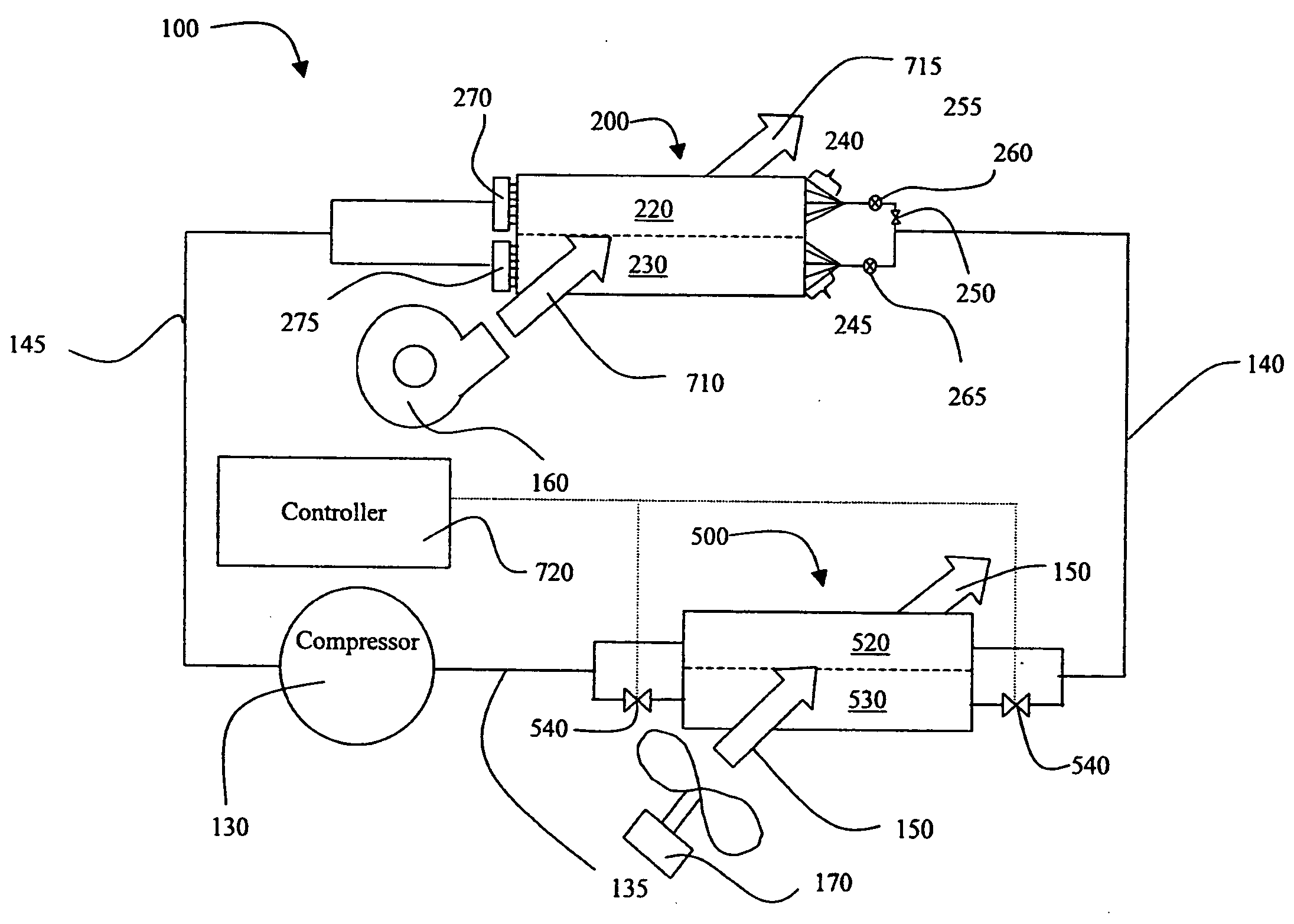
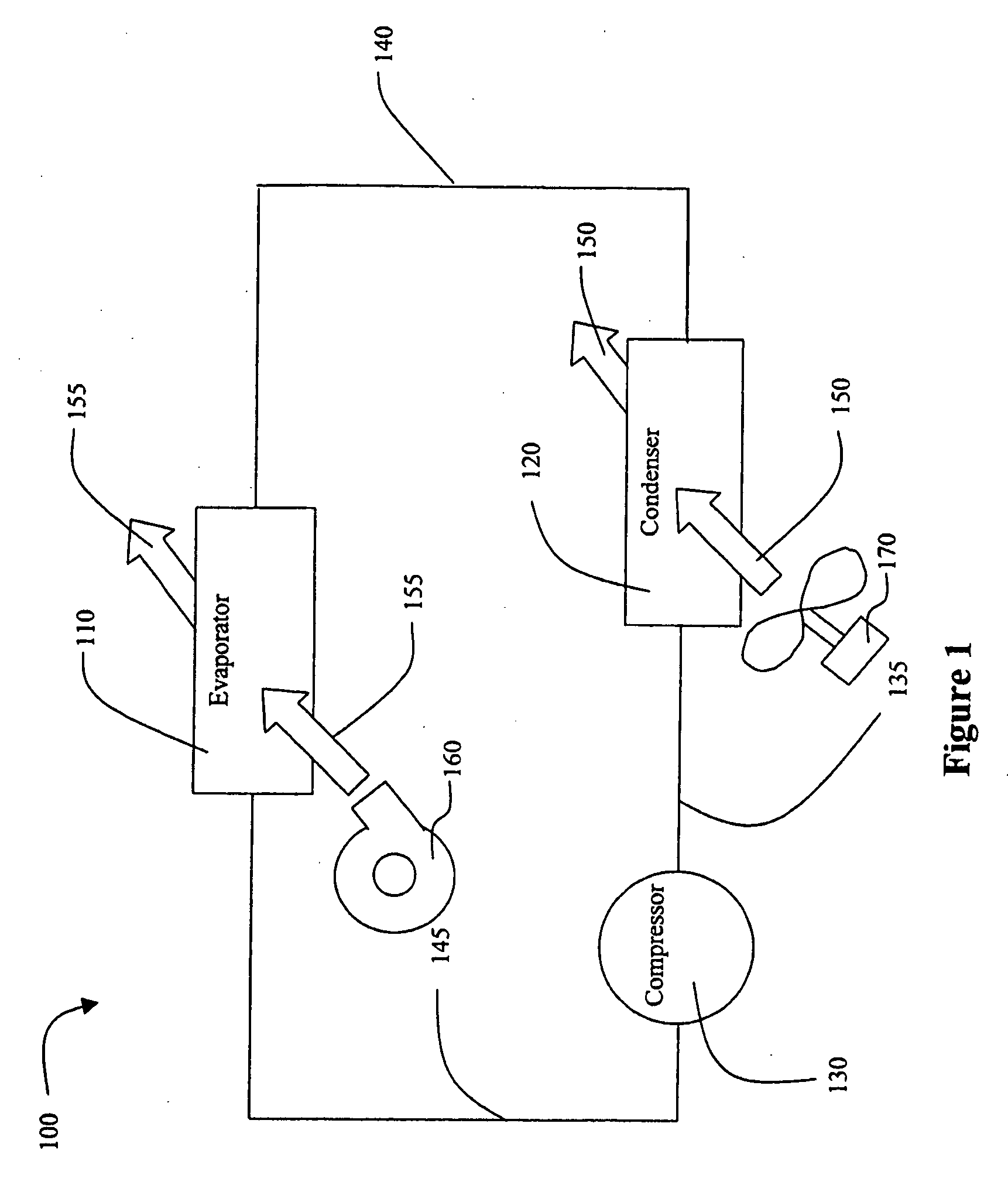
[0036]FIG. 1 illustrates a HVAC, refrigeration, or chiller system 100. Refrigeration system 100 includes a compressor 130, a condenser 120, and an evaporator 110. The compressor 130 compresses a refrigerant vapor and delivers it to the condenser 120 through compressor discharge line 135. The compressor 130 is preferably a reciprocating or scroll compressor, however, any other suitable type of compressor can be used, for example, screw compressor, rotary compressor, and centrifugal compressor. The refrigerant vapor delivered by the compressor 130 to the condenser 120 enters into a heat exchange relationship with a first heat transfer fluid 150, preferably air, and undergoes a phase change to a refrigerant liquid as a result of the heat exchange relationship with the first heat transfer fluid 150. The first heat transfer fluid 150 is moved by use of a fan 170, which moves the first heat transfer fluid 150 through the condenser 120 in a direction perpendicular the cross section of the ...


PUM


Abstract

A method for dehumidification and controlling system pressure in a refrigeration system includes providing a refrigeration system having a compressor, a condenser and an evaporator connected in a closed refrigerant loop. Each of the condenser and evaporator have a plurality of refrigerant circuits. A first heat transfer fluid is flowed over the condenser and a second heat transfer fluid is flowed over the evaporator. At least one of the refrigerant circuits of the condenser is isolated to provide a decreased amount of heat transfer area within the condenser and to increase the refrigerant pressure within the refrigeration system when the refrigerant pressure within the refrigeration system is at or below a predetermined pressure. At least one of the refrigerant circuits of the evaporator is isolated to dehumidify and maintain the temperature of the second heat transfer fluid at or above a predetermined temperature when dehumidification is required.

Description

FIELD OF THE INVENTION [0001] The present invention relates generally to heating, ventilation and air conditioner systems (HVAC), including systems that can dehumidify air. BACKGROUND OF THE INVENTION [0002] An HVAC system generally includes a closed loop refrigeration system with at least one evaporator, at least one condenser and at least one compressor. As the refrigerant travels through the evaporator, it absorbs heat from a heat transfer fluid and changes from a liquid to a vapor phase. After exiting the evaporator, the refrigerant proceeds to a compressor, then a condenser, then an expansion valve, and back to the evaporator, repeating the loop. The heat transfer fluid to be cooled (e.g. air) passes through the evaporator in a separate fluid channel and is cooled by the evaporation of the refrigerant. The heat transfer fluid can then be sent to a distribution system for cooling the spaces to be conditioned, or it can be used for other refrigeration purposes. [0003] Other refri...

Claims


Application Information

Patent Timeline
Patent Type & Authority Applications(United States)
IPC IPC(8): F25B49/00F25B41/00F25B5/00F25B39/02
CPCF24F3/153F25B5/02F25B49/027F25B2700/197F25B2600/2517F25B2600/2519F25B2700/19F25B2600/2511
Inventor KNIGHT, JOHN TERRYLANDERS, ANTHONY WILLIAMGAVULA, PATRICK GORDONPICKLE, STEPHEN BLAKE
Owner YORK INT CORP
Why Eureka
Try Eureka