
Fuel cell system with integrated fuel processor

a fuel cell and processor technology, applied in the field of fuel cell systems, can solve the problems of moderate challenges and fallen out of favor as a primary source of fuel, and achieve the effects of maximizing heat utilization, minimizing heat collection, storage and distribution systems, and minimizing catalyst or other components

Inactive Publication Date: 2007-05-31
KELLEY RICHARD H
View PDF32 Cites 67 Cited by
  • Summary
  • Abstract
  • Description
  • Claims
  • Application Information

AI Technical Summary

Benefits of technology

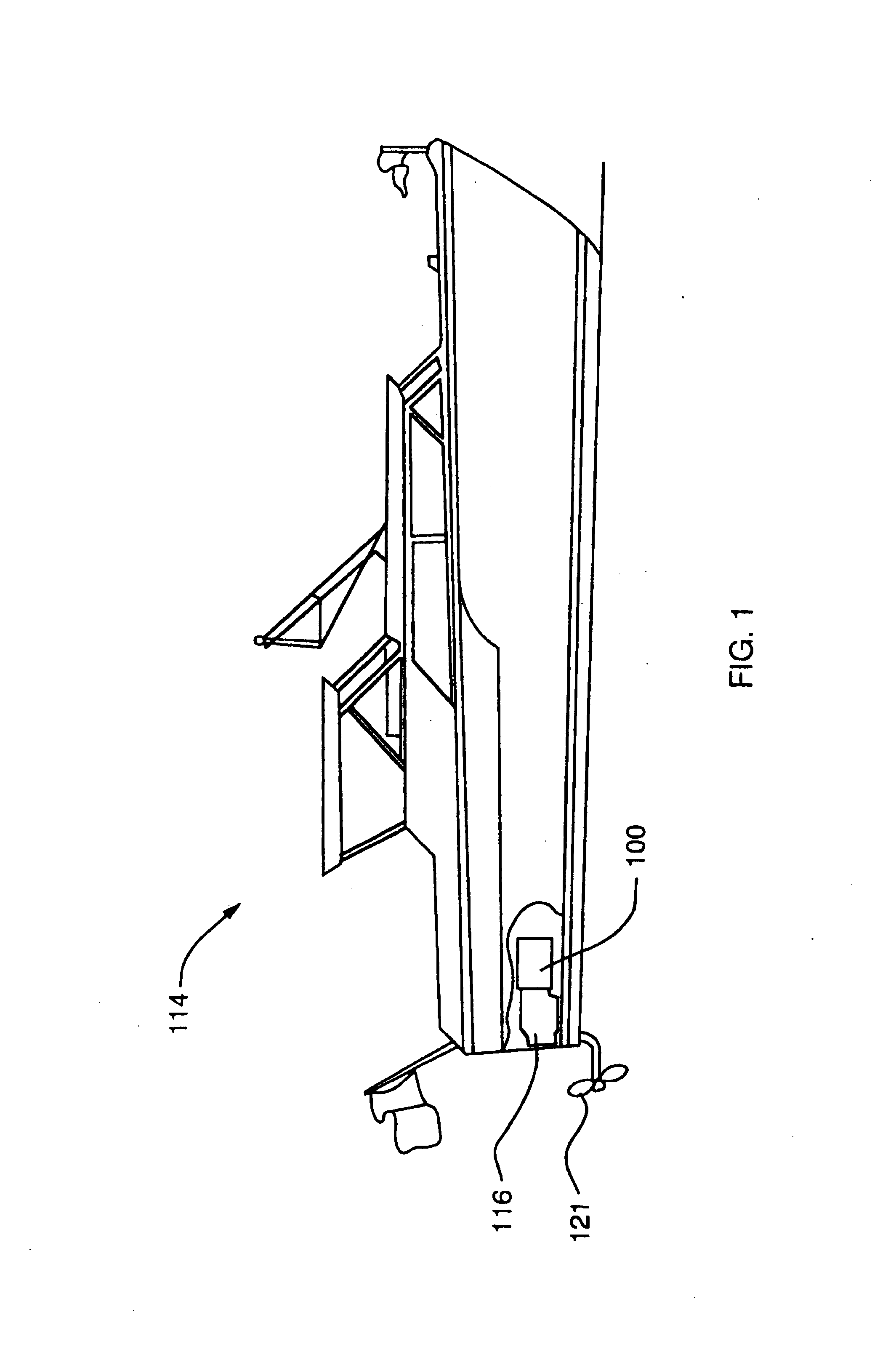
[0010] These and other objects are achieved by the present invention, which is a fuel cell system with fuel processor. The primary application of the invention is directed to marine propulsion, but not limited thereto. The system contemplates use of ethanol or biodiesel as a fuel source in the process of hydrogen generation. The system also contemplates the use of a Polymer Electrolyte Membrane (PEM) Fuel Cell. Further, the system minimizes preheating of catalysts or other components to the extent just needed to initiate and sustain the fuel processor. To that end, heat sources and sinks of the system and associated usage systems are matched so as to minimize heat collection, storage and distribution systems. It is further contemplated that water will be recycled within the system to the extent necessary to maintain a water balance in the fuel processor and the fuel cell stack(s). The system includes a water jacket to cool the fuel cell stack(s), rejection of low-grade heat to the body of water in which the vessel resides, and integrated heat recovery with exothermic and endothermic catalysts. These distinct types of catalysts are nested together to maximize heat utilization. Additionally, the fuel cell stack(s) and supporting equipment are insulated and electrically heated to prevent freezing when not in use. The fuel processor / fuel cell system components are configured to conform to available space limitations, such as the space constraints associated with a marine vessel, such as a yacht, and take advantage of the unique available space relative to available space in automobiles and other over-the-road vehicles.
[0014] It should be noted that for marine applications in particular, fuel cost and availability are two, but not the only, factors in the consideration of adopting alternative fuels suitable for use in the fuel processor. Other factors, including the environmental advantages of using alternatives to fossil fuels and the reduction of noise caused by conventional power generators, make fuel cell systems perhaps more desirable in this market than in mass mobile vehicle markets. It is also to be noted that biodiesel has high cloud points relative to petrodiesel, i.e., it tends to gel at temperatures in the range of 25 to 35 F as opposed to about −25 F for petrodiesel. Using mixtures of Ethanol and biodiesel will lower the cloud point, thereby improving cold flow properties. Therefore, in certain geographic areas, biofuel mixtures may be preferred rather than use of biodiesel only. The present invention is configured to enable the conversion of biofuels and mixtures of biofuels to produce the gases required for operation of the fuel cell.

Problems solved by technology

While there is an extensive ethanol supply and distribution system within the United States, it is primarily used for providing blends of ethanol in gasoline as an octane booster in lieu of MTBE, which has fallen out of favor due to its propensity to leak from fuel tanks and contaminate drinking water supplies.
While alcohol use in the marine industry has a long history (primarily as methanol used in on-board cooking stoves), it presents moderate challenges as a primary source of fuel owing to its relatively low energy density.

Method used


Image

  • Fuel cell system with integrated fuel processor
  • Fuel cell system with integrated fuel processor
  • Fuel cell system with integrated fuel processor

Examples


first embodiment

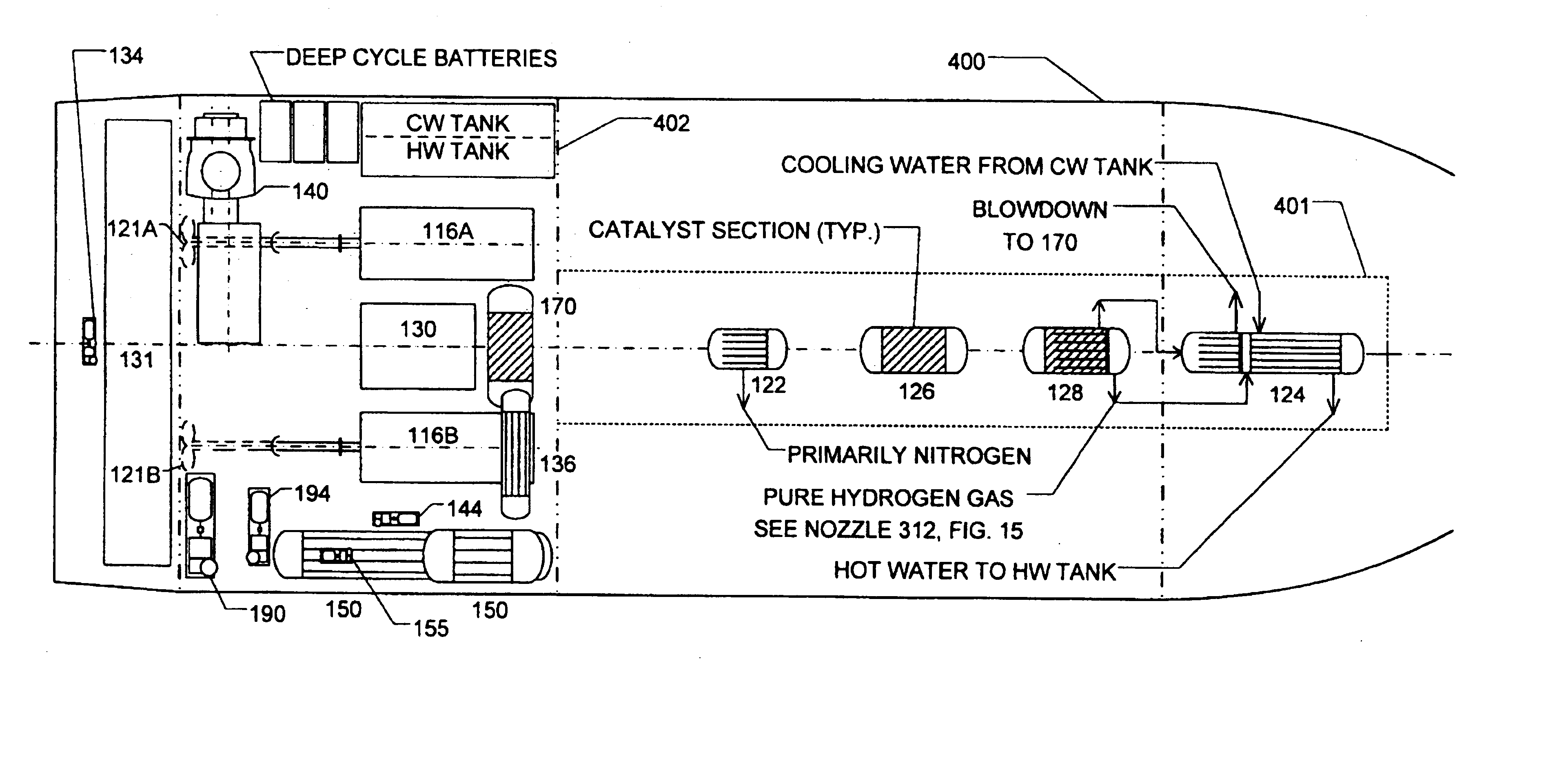
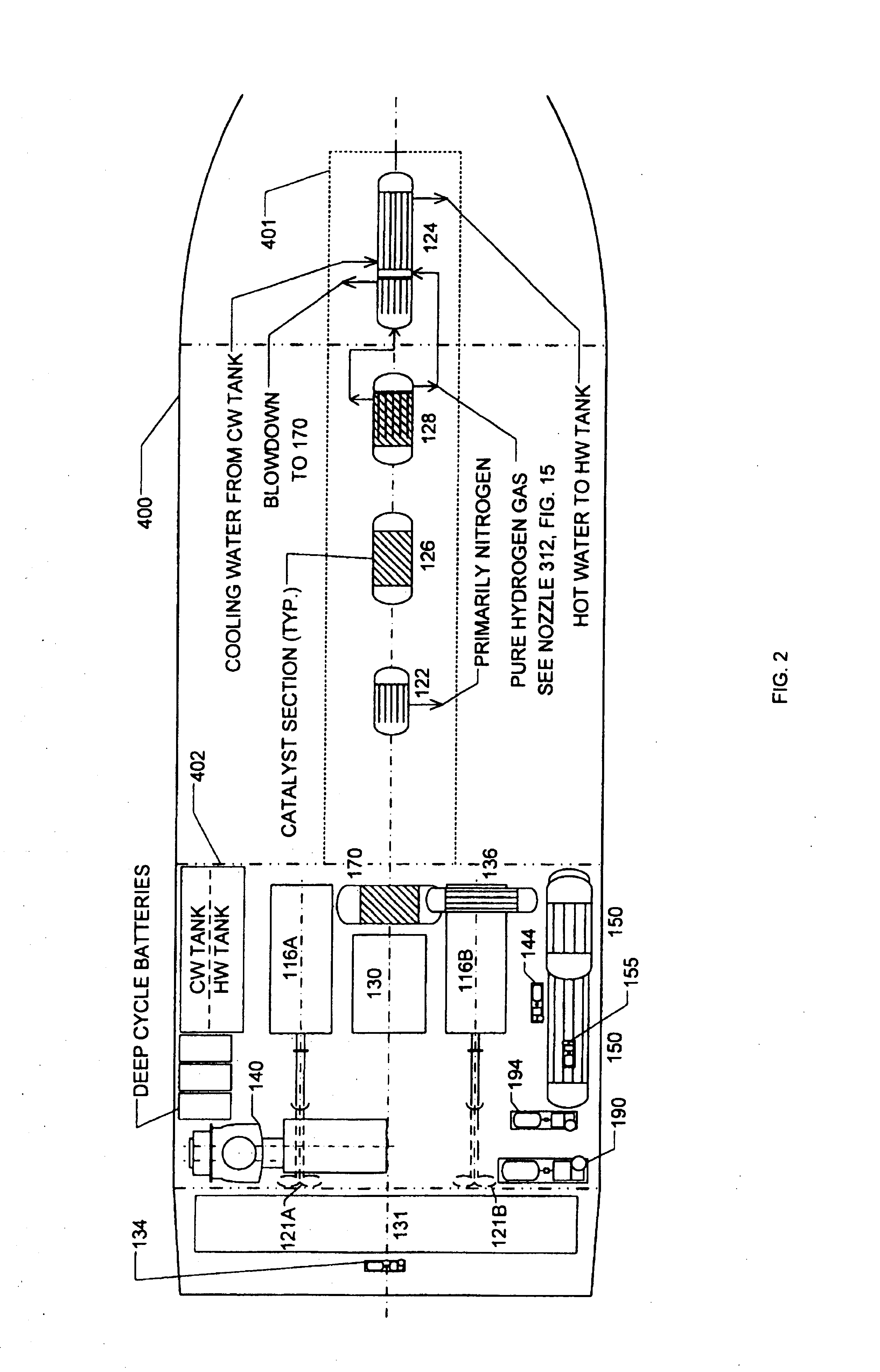
[0033] the fuel processor / fuel cell system 100 of the present invention for use in a marine vessel of relatively substantial size and a biofuel as a fuel source is shown structurally in FIG. 2 and schematically in FIG. 3 comprising FIGS. 3A and 3B. The fuel processor / fuel cell system 100 is configured and arranged to fit within the boundaries defined by the vessel. In particular, by the hull 400, a first structural stringer 401 beneath a cabin sole, a first bulkhead 402 separating the vessel's engine room from its cabin, one or more engine room structural stringers represented by second structural stringer 403 within the engine room, and a second bulkhead 404 separating the vessel's engine room from its fuel tank space. The fuel processor / fuel cell system 100 includes as primary components an oxygen membrane separator 122, a hydrogen membrane separator 124, an auto-thermal reactor 126, a water-gas shift reactor 128, and a fuel cell 130. The operation of the fuel cell 130 produces el...

second embodiment

[0044] the present invention is represented by FIGS. 4-5B, in which the fuel source is a sulfur-bearing petrodiesel fuel such as JP-8. In this embodiment, most primary components are configured, arranged and function in the manner described with respect to FIGS. 2-3B. However, in order to provide suitable efficiencies, optional sulfur guard bed 127 may be deployed to avoid poisoning the catalysts in reformer 126, water gas shift reactor 128, and fuel cell 130. The sulfur guard bed 127 operates to capture hydrogen sulfide from the sulfur-containing petrodiesel fuel by reacting the sulfur with hydrogen supplied from other components of the system. It is positioned between the output of the heat exchanger 136 at Stream 3A and as a partial introduction to Stream 6 feeding the auto-thermal reactor 126. Further, in this embodiment of the invention, the fuel cell hydrogen of Stream 19 is split into two streams; a minor stream through ducting represented by Stream 25 is redirected to the su...

third embodiment

[0045] the present invention is represented in FIGS. 6-7B, in which a biofuel is the fuel source, but the optional oxygen permeable membrane 122 is not used. This embodiment of the invention is substantially the same as the embodiment represented in FIGS. 2-3B. It is to be noted that while the embodiment of the invention represented in FIGS. 2-3B may produce the most effective fuel processor / fuel cell system, the embodiment of the invention represented in FIGS. 6-7B is also substantially effective. However, in this arrangement, air from compressor 140 is directed directly through Stream 20B to Stream 6 for introduction to the auto-thermal reactor 126, rather than introducing relatively pure oxygen thereto.


PUM

PropertyMeasurementUnit
concentrationaaaaaaaaaa
areaaaaaaaaaaa
activation energiesaaaaaaaaaa

Abstract

A fuel cell system with fuel processor for integration with a marine vessel propulsion system. The system includes an auto thermal reactor that is the fuel processor for producing hydrogen from a fuel source. The fuel source is preferably ethanol or biodiesel or a mixture thereof, but can also be a sulfur containing fuel like petrodiesel of JP-8. The system further includes a gas-water shift reactor for further production and concentration of the hydrogen from the auto thermal reactor output. The system also includes a hydrogen permeable membrane separator for generating suitable quantities of essentially pure hydrogen to the fuel cell. The system also includes an oxygen permeable membrane separator for concentrating oxygen and reducing nitrogen to improve the partial pressure of hydrogen in subsequent fuel processing steps. The system contemplates the use of a Polymer Electrolyte Membrane (PEM) fuel cell. The system minimizes preheating of catalysts or other components to the extent just needed to initiate the fuel processor. To that end, heat sources and sinks of the system and associated usage systems are matched so as to minimize heat collection, storage and distribution systems. Water is recycled within the system to the extent necessary to maintain a water balance in the fuel processor and the fuel cell stack(s). The system includes cooling of the fuel cell stack(s) and integrated heat recovery with exothermic and endothermic catalysts. The fuel processor / fuel cell system components are configured to conform to and take advantage of the available space and limitations, such as the space constraints and opportunities associated with a marine vessel.

Description

BACKGROUND OF THE INVENTION [0001] 1. Field of the Invention [0002] The present invention relates to fuel cell systems. More particularly, the present system relates to fuel cell systems used as propulsion for marine vessels. Still more particularly, the present invention relates to the integration of fuel cells, particularly Polymer Electrolyte Membrane (PEM) fuel cells, into marine propulsion compartments. The present invention includes a biofuel processor integrated with a PEM fuel cell and electric propulsion drive and AC / DC electric power systems. [0003] 2. Description of the Prior Art [0004] In view of the many limitations associated with the use of conventional fossil fuels as a source of power for everything from power generation systems to mechanical equipment to vehicles, much effort has been focused on the use of alternative fuel sources. Among others, fuel cells have been shown to be of some promise. In simple terms, a fuel cell operates much like a battery. It includes ...

Claims


Application Information

Patent Timeline
Patent Type & Authority Applications(United States)
IPC IPC(8): H01M8/06H01M8/04
CPCC01B3/382C01B3/48C01B13/0251C01B2203/0244C01B2203/0283C01B2203/0288C01B2203/0405C01B2203/0495C01B2203/066C01B2203/0894C01B2203/1229C01B2203/1247C01B2203/1258C01B2203/127C01B2203/1294C01B2210/0046C01B2210/0053H01M8/04029H01M8/04097H01M8/04164H01M8/0612H01M8/0687Y02E60/50Y02P20/10
Inventor KELLEY, RICHARD H.
Owner KELLEY RICHARD H
Learn More