Corona suppression at the high voltage joint through introduction of a semi-conductive sleeve between the central electrode and the dissimilar insulating materials

a technology of suppression and high voltage joint, which is applied in the manufacture of sparking plugs, corona discharge, electrical apparatus, etc., can solve the problems of uneven electrical field and air gaps at the interface, and difficult control, so as to reduce stress, reduce peak electric field, and increase the effect of electric field

Active Publication Date: 2017-01-26
TENNECO INC
View PDF0 Cites 14 Cited by
  • Summary
  • Abstract
  • Description
  • Claims
  • Application Information

AI Technical Summary

Benefits of technology

[0010]The semi-conductive sleeve relieves stress and stabilizes the electrical field between the different materials disposed radially across the corona igniter assembly, where more air gaps or changes in geometry leading to increases in electric field typically exist. More specifically, the semi-conductive sleeve minimizes the peak electric field within the corona igniter assembly by contrasting the electric charge concentration in any air gaps located along the high voltage center electrode or ceramic insulator. The voltage drop through the semi-conductive sleeve is significant, and thus the voltage peak at the interface between the semi-conductive sleeve and the adjacent materials is lower than the voltage peak between the high voltage center electrode and the ceramic insulator would be without the semi-conductive sleeve. Studies show that the semi-conductive sleeve performs like an actual conductor, with limited loss of power, when fed with a high frequency and high voltage (HV-HF).
[0011]The semi-conductive sleeve also conducts charge away and relieves any cavities from static electrical charge that could generate unwanted corona discharge. Furthermore, the semi-conductive sleeve is typically formed of a compliant material, and thus minimizes the amount or volume of air gaps along the interfaces between the high voltage center electrode and the ceramic insulator. In summary, by preventing the unwanted corona discharge, the life of the materials can be extended and the energy can be directed to the corona discharge formed at the firing end, which in turn improves the performance of the corona igniter assembly.

Problems solved by technology

However, such control is oftentimes difficult to achieve due to air gaps located between the components of the corona igniter assembly where unwanted corona discharge tends to form.
For example, although the use of multiple insulators formed of different materials provides improved efficiency, robustness, and overall performance, the metallic shielding and the different electrical properties between the insulator materials leads to an uneven electrical field and air gaps at the interfaces.
The dissimilar coefficients of thermal expansion and creep between the insulator materials can also lead to air gaps at the interfaces when operating in the −40° C. to 150° C. temperature range.
The high voltage and frequency applied to the corona igniter assembly ionizes the trapped air causes unwanted corona discharge.
Such corona discharge can cause material degradation and hinder the performance of the corona igniter assembly.
In addition, the different materials disposed radially across the assembly can lead to an uneven distribution of electrical field strength between those materials.

Method used


Image

  • Corona suppression at the high voltage joint through introduction of a semi-conductive sleeve between the central electrode and the dissimilar insulating materials
  • Corona suppression at the high voltage joint through introduction of a semi-conductive sleeve between the central electrode and the dissimilar insulating materials
  • Corona suppression at the high voltage joint through introduction of a semi-conductive sleeve between the central electrode and the dissimilar insulating materials

Examples


Embodiment Construction

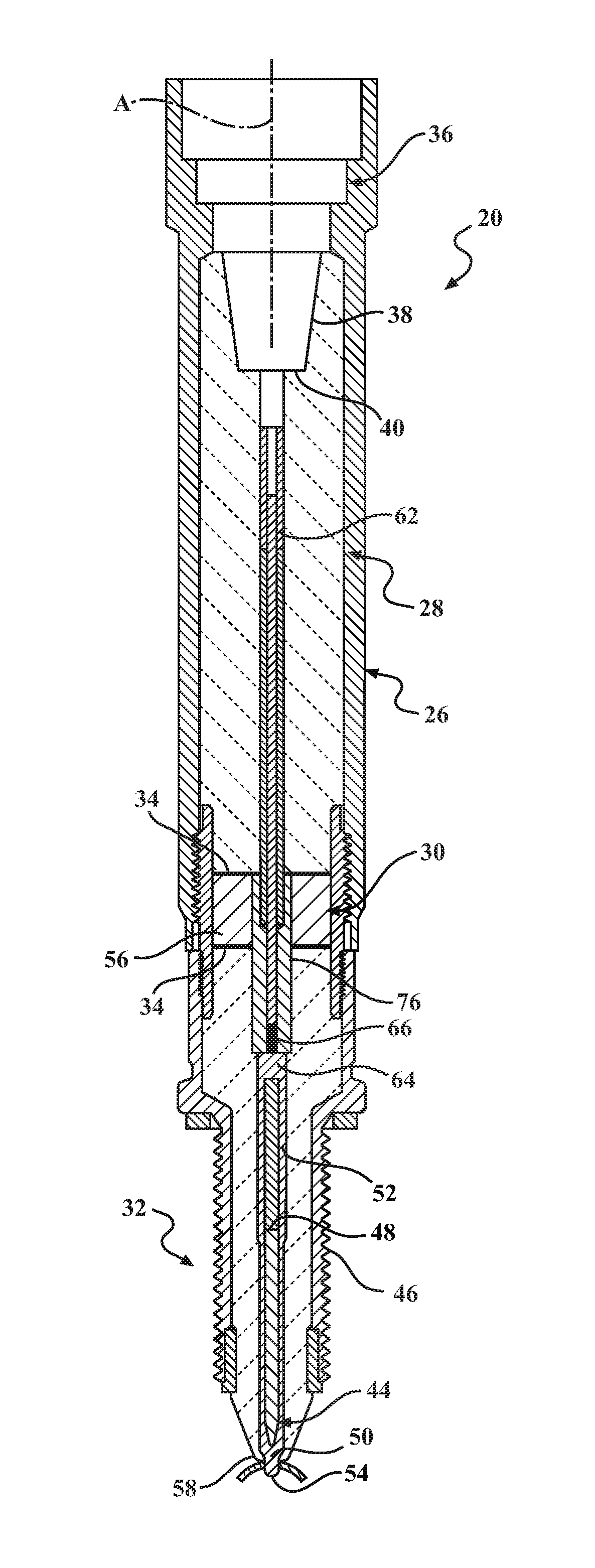
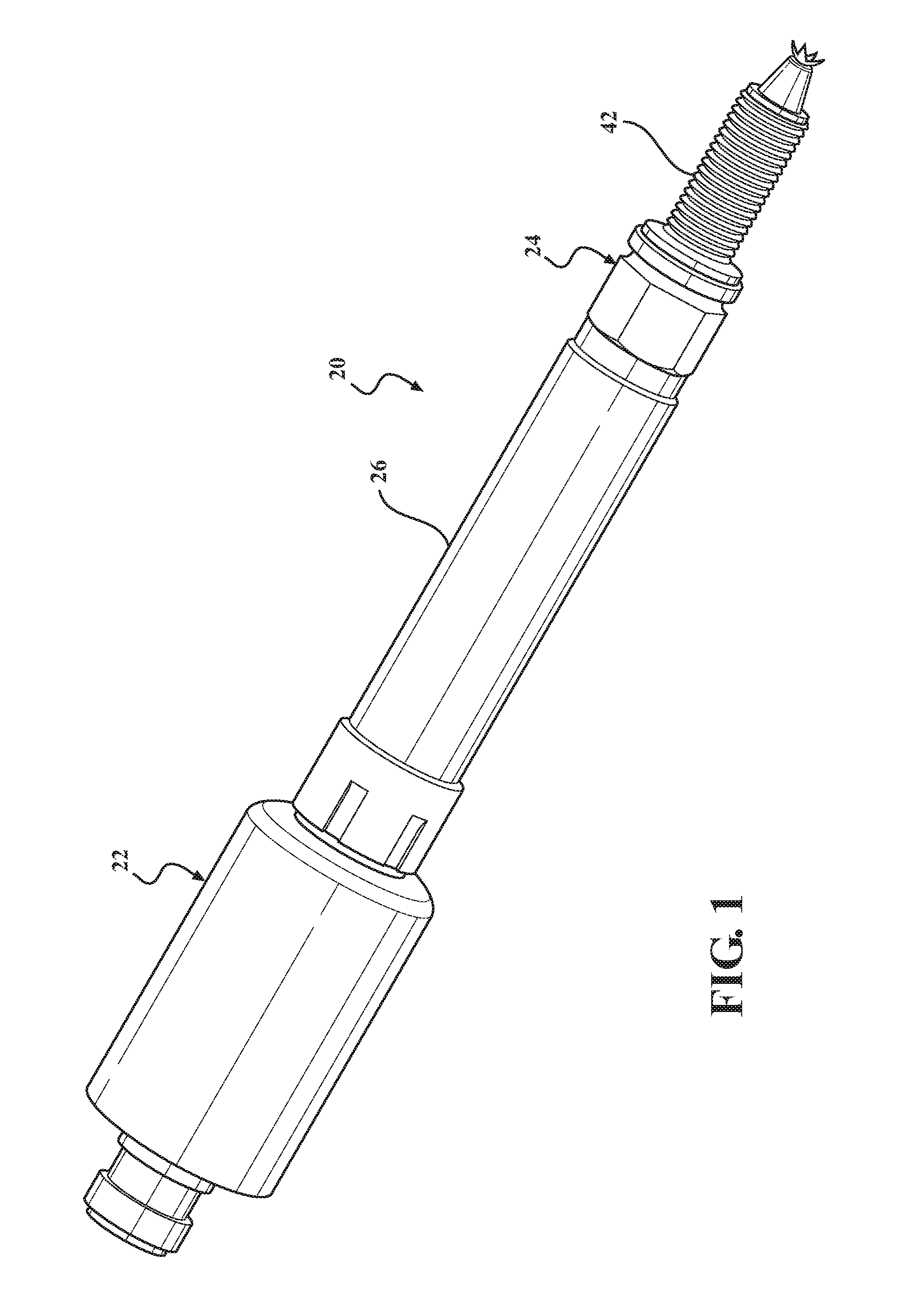
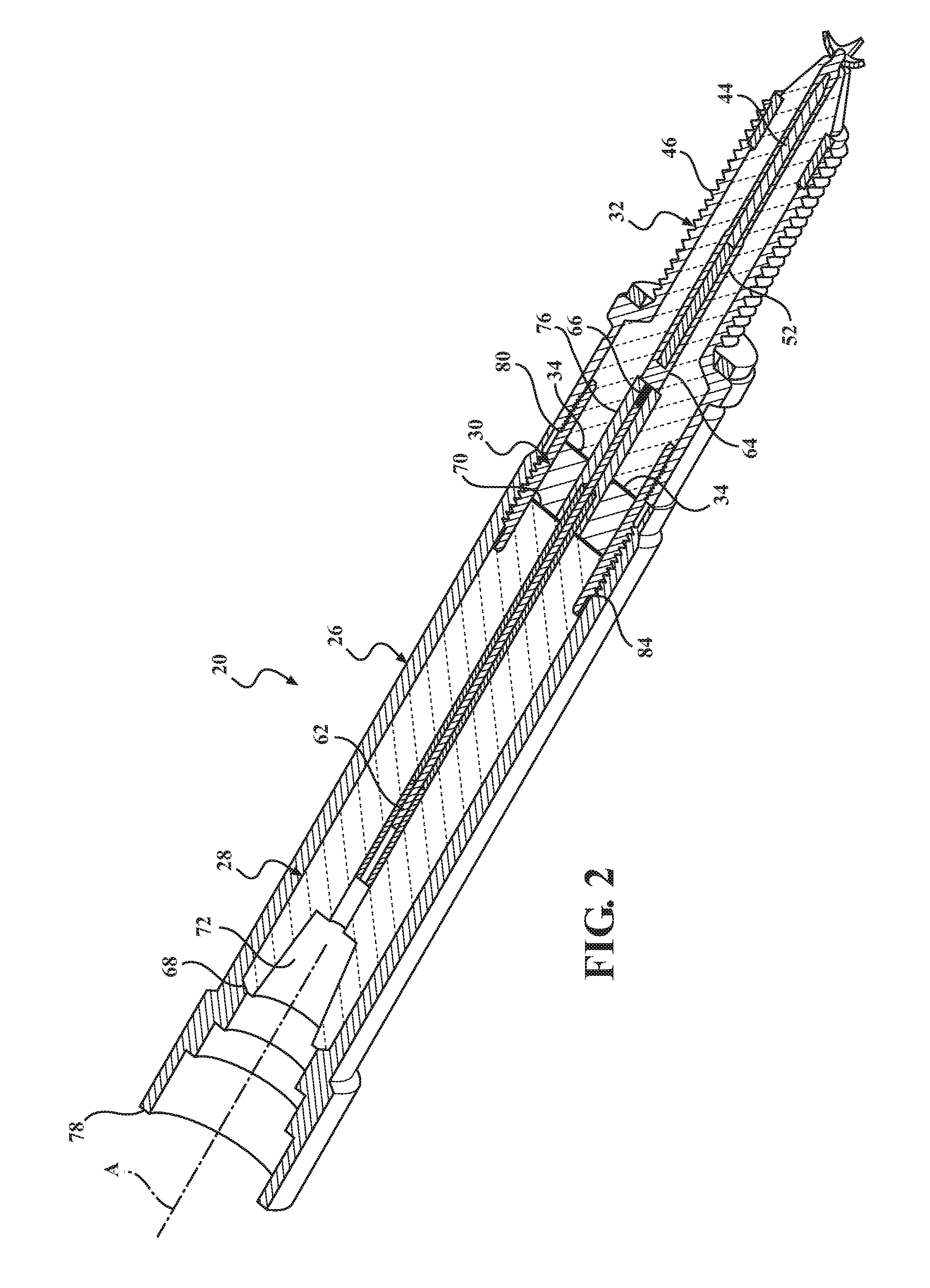
[0042]A corona igniter assembly 20 for receiving a high radio frequency voltage and distributing a radio frequency electric field in a combustion chamber containing a mixture of fuel and gas to provide a corona discharge is generally shown in FIG. 1. The corona igniter assembly 20 includes an ignition coil assembly 22, a firing end assembly 24, and a metal tube 26 surrounding and coupling the ignition coil assembly 22 to the firing end assembly 24. The corona igniter assembly 20 also includes a high voltage insulator 28 and an optional dielectric compliant insulator 30 each disposed between the ignition coil assembly 22 and a ceramic insulator 32 of the firing end assembly24, inside of the metal tube 26. A high voltage center electrode 62 connects the ignition coil assembly 22 to the firing end assembly 24. A semi-conductive sleeve 76 extends continuously along the interfaces between the different insulators 28, 30, 32. The semi-conductive sleeve 76 dampens the peak electric field a...


PUM


Abstract

A corona ignition assembly comprising a plurality of different insulators disposed between an ignition coil assembly and firing end assembly is provided. A high voltage center electrode extends longitudinally between an igniter central electrode and the ignition coil assembly. A high voltage insulator formed of a fluoropolymer surrounds the high voltage center electrode, and a firing end insulator firing of alumina surrounds the igniter central electrode. A sleeve formed of a semi-conductive and complaint material, such as silicone rubber with conductive filler, is disposed radially between the electrodes and adjacent insulators. The sleeve fills air gaps and minimizes the peak electric field within the corona igniter assembly. The sleeve is able to prevent unwanted corona discharge, and thus extends the life of the materials and directs energy to the firing end.

Description

CROSS-REFERENCE TO RELATED APPLICATION[0001]This U.S. patent application claims the benefit of U.S. Provisional Patent Application No. 62 / 138,642, filed Mar. 26, 2015, which is incorporated herein by reference in its entirety.BACKGROUND OF THE INVENTION[0002]1. Field of the Invention[0003]This invention relates generally to corona ignition assemblies, and methods of manufacturing the corona ignition assemblies.[0004]2. Related Art[0005]Corona igniter assemblies for use in corona discharge ignition systems typically include an ignition coil assembly attached to a firing end assembly as a single component. The firing end assembly includes a center electrode charged to a high radio frequency voltage potential, creating a strong radio frequency electric field in a combustion chamber. The electric field causes a portion of a mixture of fuel and air in the combustion chamber to ionize and begin dielectric breakdown, facilitating combustion of the fuel-air mixture. The electric field is pr...

Claims


Application Information

Patent Timeline
Patent Type & Authority Applications(United States)
IPC IPC(8): H01T19/00H01T21/02H01T13/20
CPCH01T19/00H01T21/02H01T13/20H01T13/34H01T13/44H01T13/50
Inventor MIXELL, KRISTAPHERPHILLIPS, PAULMILAN, GIULIODAL RE, MASSIMO
Owner TENNECO INC
Why Eureka
Try Eureka