Control Unit For Fuel-Cell Power Generation Apparatus, And Control Method, Control Program And Computer-Readable Record Medium With Control Program For The Same

a technology of power generation apparatus and control unit, which is applied in the direction of lighting and heating apparatus, heating types, domestic hot water supply systems, etc., can solve the problems of insufficient supply of hot water heat quantity, insufficient efficiency, and insufficient supply of hot water heat consumption of hot water supply equipment, so as to reduce the energy consumption of fuel-cell systems, save energy, and operate efficiently

Inactive Publication Date: 2008-02-14
PANASONIC CORP
View PDF1 Cites 12 Cited by
  • Summary
  • Abstract
  • Description
  • Claims
  • Application Information

AI Technical Summary

Benefits of technology

[0010] According to the present invention, in terms of the fuel-cell system energy calculated in each of the plurality of generated-power command patterns obtained from a combination of a start time and a stop time of the fuel-cell power generation apparatus, the generated-power command pattern which minimizes the fuel-cell system energy is acquired. At the corresponding start time, the fuel-cell power generation apparatus is started, and it is stopped at the corresponding stop time. Therefore, the fuel-cell power generation apparatus can be efficiently operated according to a power consumption and a supplied hot-water heat consumption which are different in each home. This makes it possible to realize the saving of energy.

Problems solved by technology

However, in the above described conventional control methods for a fuel-cell power generation apparatus, only either a supplied hot-water heat consumption or a power consumption which is spent in a home is taken into account.
Therefore, if the power to be generated is controlled in consideration of only a supplied hot-water heat consumption, the generated power cannot be equivalent to the power used by electric equipment.
For example, if the generated power is greater than the power consumption, then an inefficient conversion into heat may be forced, resulting in a drop in efficiency.
On the other hand, if the generated power is controlled taking only a power consumption into account, the generated supplied hot-water heat quantity cannot be equal to the supplied hot-water heat consumption used by hot-water supply equipment.
Besides, if the hot-water storage tank is filled with hot water, the fuel-cell power generation apparatus has to be fully halted so that heat will not be generated any longer.
When it is started again, a rising loss is caused, thus deteriorating the energy-saving capability.

Method used


Image

  • Control Unit For Fuel-Cell Power Generation Apparatus, And Control Method, Control Program And Computer-Readable Record Medium With Control Program For The Same
  • Control Unit For Fuel-Cell Power Generation Apparatus, And Control Method, Control Program And Computer-Readable Record Medium With Control Program For The Same
  • Control Unit For Fuel-Cell Power Generation Apparatus, And Control Method, Control Program And Computer-Readable Record Medium With Control Program For The Same

Examples


first embodiment

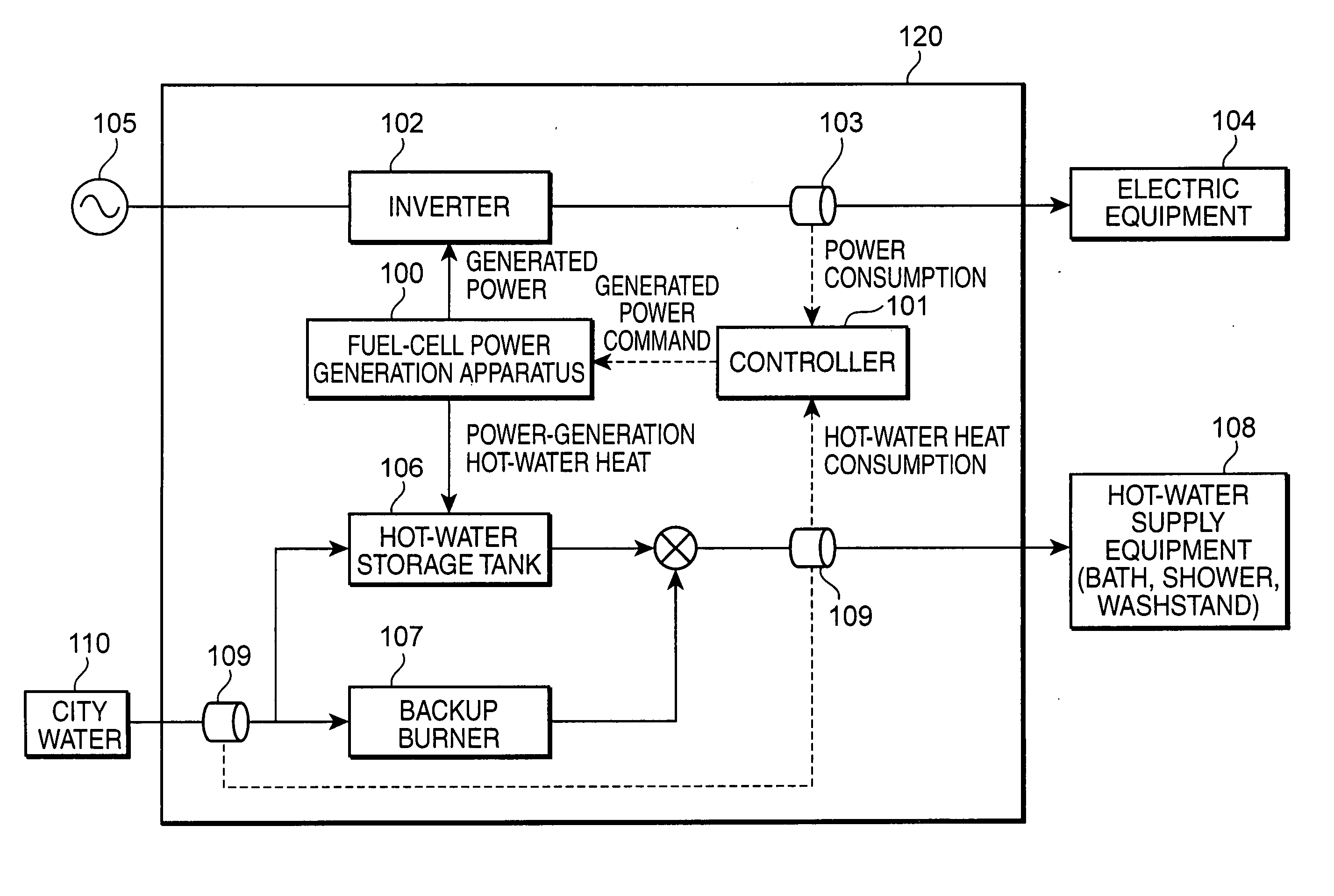
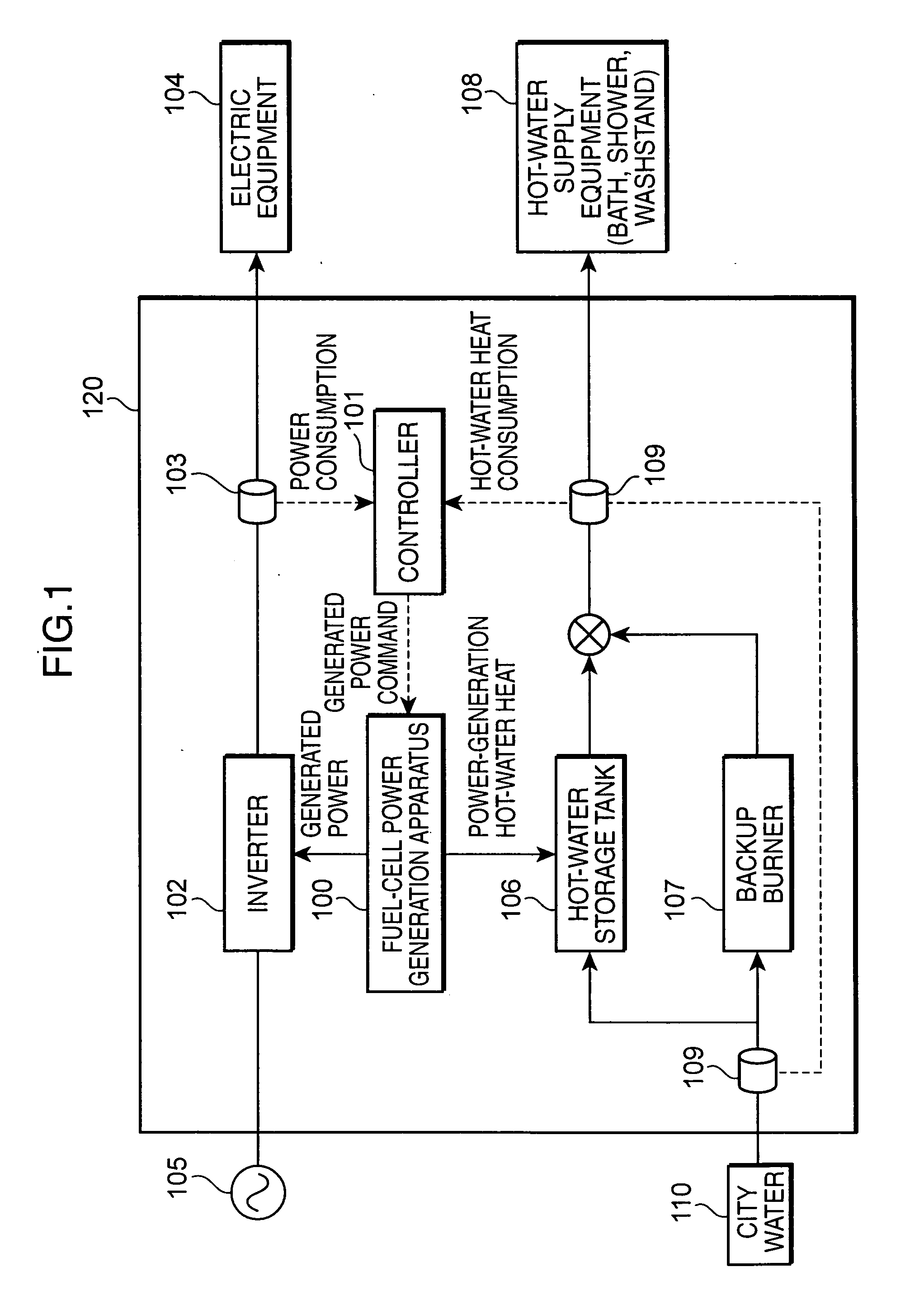
[0025]FIG. 1 is a block diagram, showing the whole configuration of a fuel-cell power generation system according to the present invention. A fuel-cell power generation system 120 shown in FIG. 1 is configured by a fuel-cell power generation apparatus 100, a controller 101, an inverter 102, a wattmeter 103, a hot-water storage tank 106, a backup burner 107, and a supplied hot-water calorimeter 109.

[0026] To an electric power system in a home, there are connected the fuel-cell power generation apparatus 100, the inverter 102, electric equipment 104, and a commercial power source 105. The wattmeter 103 measures electric power used by the electric equipment 104. The electric equipment 104 is, for example, a household electrical appliance such as a refrigerator and a washing machine. It includes various types of equipment in which electricity is used.

[0027] To a hot-water supply system in a home, there are connected the fuel-cell power generation apparatus 100, the hot-water storage t...

second embodiment

[0101] Next, a second embodiment of the present invention will be described. In the first embodiment, the start time s1 and the stop time e1 in accordance with the demand of power and the demand of supplied hot-water in each home are outputted to the fuel-cell power generation apparatus 100. Thereby, the fuel-cell power generation apparatus 100 is efficiently operated, so that energy can be saved. In contrast, in the second embodiment, the case where the fuel-cell power generation apparatus 100 is stopped when a hot-water storage tank fills is added to the evaluation of a calculation of the fuel-cell system energy.

[0102]FIG. 7 is a block diagram, showing the configuration of a controller 101 according to the second embodiment. In FIG. 7, several component elements have the same configuration as those of the controller according to the first embodiment shown in FIG. 2, and thus, their description is omitted. Besides, the whole configuration of a fuel-cell power generation system acc...

third embodiment

[0150] Next, a third embodiment of the present invention will be described. In the second embodiment, if the hot-water storage tank is filled, the fuel-cell power generation apparatus 100 is stopped. In contrast, in the third embodiment, the fuel-cell power generation system 120 further includes a radiator which radiates heat from the hot-water storage tank. Even if the hot-water storage tank fills, then without stopping, the fuel-cell power generation apparatus 100 keeps operating while radiating some heat of the hot-water storage tank.

[0151]FIG. 9 is a block diagram, showing the whole configuration of a fuel-cell power generation system according to the third embodiment of the present invention. A fuel-cell power generation system 120 shown in FIG. 9 is configured by a fuel-cell power generation apparatus 100, a controller 101, an inverter 102, a wattmeter 103, a hot-water storage tank 106, a backup burner 107, a supplied hot-water calorimeter 109, and a radiator 130. In FIG. 9, ...


PUM

PropertyMeasurementUnit
timeaaaaaaaaaa
timeaaaaaaaaaa
timeaaaaaaaaaa

Abstract

A control unit is provided which is capable of operating a fuel-cell power generation apparatus efficiently according to a power consumption and a supplied hot-water heat consumption which are different in each home, and realizing the saving of energy.
A generated-power command-pattern creation section 212 creates a plurality of generated-power command patterns which are obtained from a combination of a start time and a stop time of the fuel-cell power generation apparatus, based on a power-consumption prediction value; a hot-water storage-tank heat-quantity calculation section 215 calculates a stored hot-water heat quantity for a predetermined period in a hot-water storage tank, based on a supplied hot-water heat-consumption prediction; a fuel-cell system-energy calculation section 214 calculates fuel-cell system energy which indicates the energy of a fuel required in hot-water supply equipment and electricity required in electric equipment when the fuel-cell power generation apparatus is operated in each generated-power command pattern; and in terms of the fuel-cell system energy in each of the plurality of generated-power command patterns, an optimum command-pattern selection section 217 operates the fuel-cell power generation apparatus in the generated-power command pattern which minimizes the fuel-cell system energy.

Description

TECHNICAL FIELD [0001] The present invention relates to a control unit for a fuel-cell power generation apparatus which generates electric power and supplies it to electric equipment, and using simultaneously generated heat, supplies hot water to hot-water supply equipment. For the same purpose, it also relates to a control method, a control program, and a computer-readable record medium in which a control program is recorded. BACKGROUND ART [0002] Conventionally, a fuel-cell power generation apparatus has been known which, using a fuel gas, generates electricity in a fuel battery and supplies electric power and hot water. In order to enhance energy efficiency by making good use of electric power and hot water supplied by such a fuel-cell power generation apparatus, it is desirable that the power generated by a fuel battery be equivalent to the power used by electric equipment. Desirably, the concurrently generated hot water should also be equal to the quantity of hot water used by ...

Claims


Application Information

Patent Timeline
Patent Type & Authority Applications(United States)
IPC IPC(8): H01M8/04F24D18/00
CPCF24D17/001F24H2240/10H01M8/04052H01M8/04604H01M8/04955Y02B90/16H01M2250/405Y02B90/14H01M8/04992Y02E60/50H01M2250/10Y02B30/18Y02B90/10F24D2101/30F24D18/00
Inventor MATSUBAYASHI, SHIGEAKIOZEKI, MASATAKATANAKA, YOSHIKAZU
Owner PANASONIC CORP
Why Eureka
Try Eureka