Apparatus and method for continuous separation of magnetic particles from non-magnetic fluids

a technology of magnetic particles and fluids, applied in the direction of separation processes, filtration separation, moving filter elements, etc., can solve the problems of high overflow of rich materials from the reactors employed, process and quasi-continuous versions of catalysts are plugged too quickly, and the application of fischer-tropsch is not well suited to it. , to achieve the effect of reducing frictional drag, reducing catalyst clogging, and increasing feed ra

Inactive Publication Date: 2010-08-12
RES USA LLC
View PDF4 Cites 14 Cited by
  • Summary
  • Abstract
  • Description
  • Claims
  • Application Information

AI Technical Summary

Benefits of technology

[0012]A dispersion of magnetic particles in a non-magnetic fluid is passed through an empty chamber made from non-magnetic materials which are located between the poles of a magnet which produces a uniform magnetic field directed transverse to the direction of flow. The connecting tubing, pumps, valves, and separation vessel may be thermally insulated and of such construction as to withstand the pressure and temperature differences between those of the operating system and the ambient environment (e.g., temperatures up to and including 500° F. and pressures up to and including 500 psi). There are no magnetic elements built inside the separation chamber. The separation chamber is empty except for the non-magnetic inlet pipes and the slurry contained therein. The slurry of fluid containing the magnetic particles is released into the chamber from above through downwardly directed inlet ports located against the inside walls of the separation chamber adjacent to the magnet pole faces at an elevation below the top and above the bottom of the chamber. The poles may be so disposed that the lines of the magnetic field are substantially perpendicular to the length of the separation chamber. Exit ports are located at the top and the bottom of the chamber. The magnetic particles, which themselves may be clusters of particles, become magnetized by the externally applied magnetic field as they enter the separation chamber and attract one another to form agglomerates or chains of particles joined end to end strung out along the lines of the magnetic field. For example, the magnetic field is applied transverse to the direction of flow which is along the axis of the separation chamber. The slurry of particles enters the separation chamber as plumes of slurry extending downward along the inside walls of the chamber nearest the magnet poles. The plumes of flow bring the magnetic particles into the separation chamber where they subsequently form chains of agglomerates. The chained particles, in turn, provide a source of intense gradient magnetic fields for capture of additional particles. Simultaneously, the flushing action of the plumes of slurry prevents the chains of magnetic particles from sticking to the inside walls of the separation chamber by sweeping the chained particles downward to the exit port at the bottom of the separation chamber. By this action, the unique apparatus is continuously creating new capture surfaces and retaining fresh particles from flow while simultaneously removing the captured particles. This creates a stream of fluid diminished in particle concentration which, by buoyancy, emerges from the top of the apparatus.
[0013]The slurry may be comprised of both magnetic and non-magnetic particles suspended in a non-magnetic fluid. The elevation at which the slurry flow is released into the separation chamber is adjusted so as not to stir up particles which have concentrated in the bottom of the separation chamber where magnetic particles exit the apparatus. Non-magnetic particles and fluid follow the lines of flow and exit at the top and the bottom of the apparatus in relation to the rates of flow. The bottom of the chamber extends below the bottom edge of the magnet return frame and is sloped to a final exit diameter outside of the magnetic field region. This slope is introduced to minimize effects such as frictional drag which would tend to hold the magnetic particles inside the separation chamber. An overflow outlet port is located at the top of the chamber where non-magnetic fluid and some particles flow from the separator. The upper surfaces of the magnet poles terminate abruptly at a distance below the top of the separation chamber for the purpose of creating a field gradient which serves to keep magnetic particles from exiting the top of the separator.
[0014]The lower edges of the magnet poles extend to the bottom of the straight section of the separation chamber below the bottom of the magnet iron return frame and are tapered outward. The elongated poles serve to lengthen the flow path through the magnetic field which in turn permits higher rates of feed to the separation chamber without the plumes of slurry disturbing the concentrated magnetic particles located at the bottom of the chamber. Additionally, the outward slope of the poles minimizes the upward directed magnetic force which would hold magnetic particles in the lower regions of the separator and cause plugging.
[0015]Flow created by the source, hydrostatic pressure, and / or optional external means, such as a pump, can be employed to force the fluid from the slurry source through the separation chamber. Valves can be employed with the external flow source, hydrostatic pressure, and / or pump to control the rates of high-solids underflow and low-solids overflow, respectively. Depending on the length of the separation chamber and underflow impedance, flow ratios (underflow rate divided by the overflow rate) generally greater than five, provide flows strong enough to sweep the chained particles downward without disrupting the magnetic particles in the bottom of the separation chamber. Flow ratios greater than or equal to ten are especially preferred. The magnetic fields employed need only be large enough to magnetize the particles to a degree which will permit mutual attraction and formation of stable agglomerates. For strongly magnetic particles which exhibit ferromagnetism or other forms of collective magnetism, the magnetic field need only be strong enough to achieve a reasonable degree of magnetic saturation. In the case of separation of nominal 0.4 micron mean-sized agglomerates of 2 to 60 nanometer sized iron catalyst particles with magnetic moments nominally 50-60 emu / g from Fischer-Tropsch wax, nominally 30% of the particles were separated in a magnetic field of 500 gauss while greater than 96% separation of catalysts from the wax product has been achieved in magnetic fields of nominally 1500 gauss. The filtration rate for both cases was between 110 and 130 kg / min / m2. It can be argued from Stokes' Law that the size of particles that can be separated can be reduced and that less magnetic particles, for example, 1 emu / g, and paramagnetic particles can also be separated by employing magnetic fields stronger than 1500 gauss, for example, up to 50,000 gauss. This includes paramagnetic particles and iron, cobalt, and nickel and their compounds.

Problems solved by technology

418-425 (September, 1976)] is not well suited to the Fischer-Tropsch application because of the strongly magnetic character of the catalyst particles employed.
Additionally, the concentration of these particles in the wax-rich overflow from the reactors employed is so high that the batch process and quasi-continuous versions of it are plugged with the catalyst too rapidly for commercial application.
No means are employed to control the rate of flow of the two streams exiting the coalescer.
This results in a possible buildup of catalyst particles in the bottom of the chamber which can lead to plugging.
While this results in strong magnetic forces for capture, it can also make continuous operation problematical because of the tendency of solid particles to stick and not to release from the magnetized capture surfaces.
It is claimed that the added use of the wire filter permits a speed up of the overflow rate, without revealing what the increase in the overflow rate is, but this happens at the expense of sacrificing the continuous nature of the process.
The throughput limitation of the dynamic settler is impractical because of the high temperature and pressure employed in the Fischer-Tropsch synthesis.
The size and number of dynamic settlers alone would make the method cost prohibitive.

Method used


Image

  • Apparatus and method for continuous separation of magnetic particles from non-magnetic fluids
  • Apparatus and method for continuous separation of magnetic particles from non-magnetic fluids
  • Apparatus and method for continuous separation of magnetic particles from non-magnetic fluids

Examples


example 1

Typical Experiment

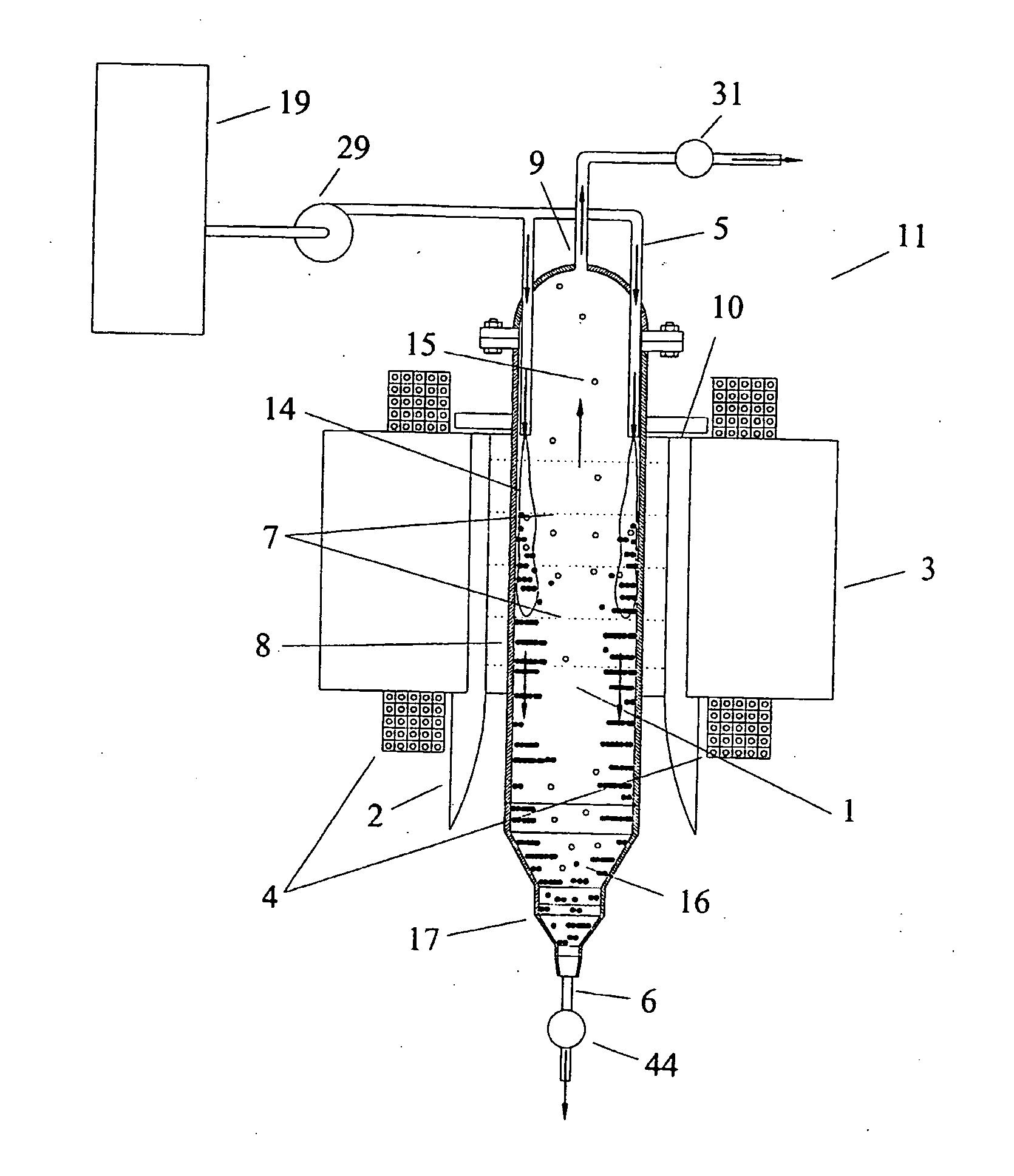
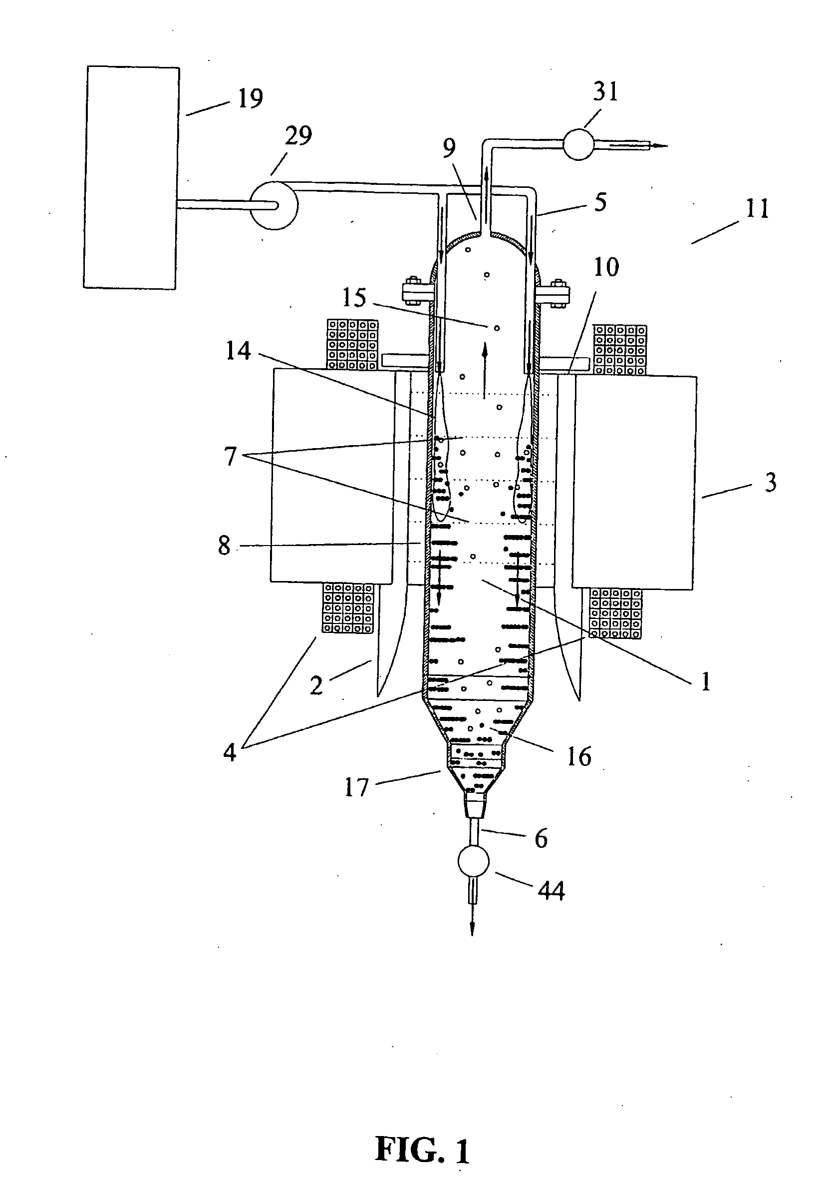
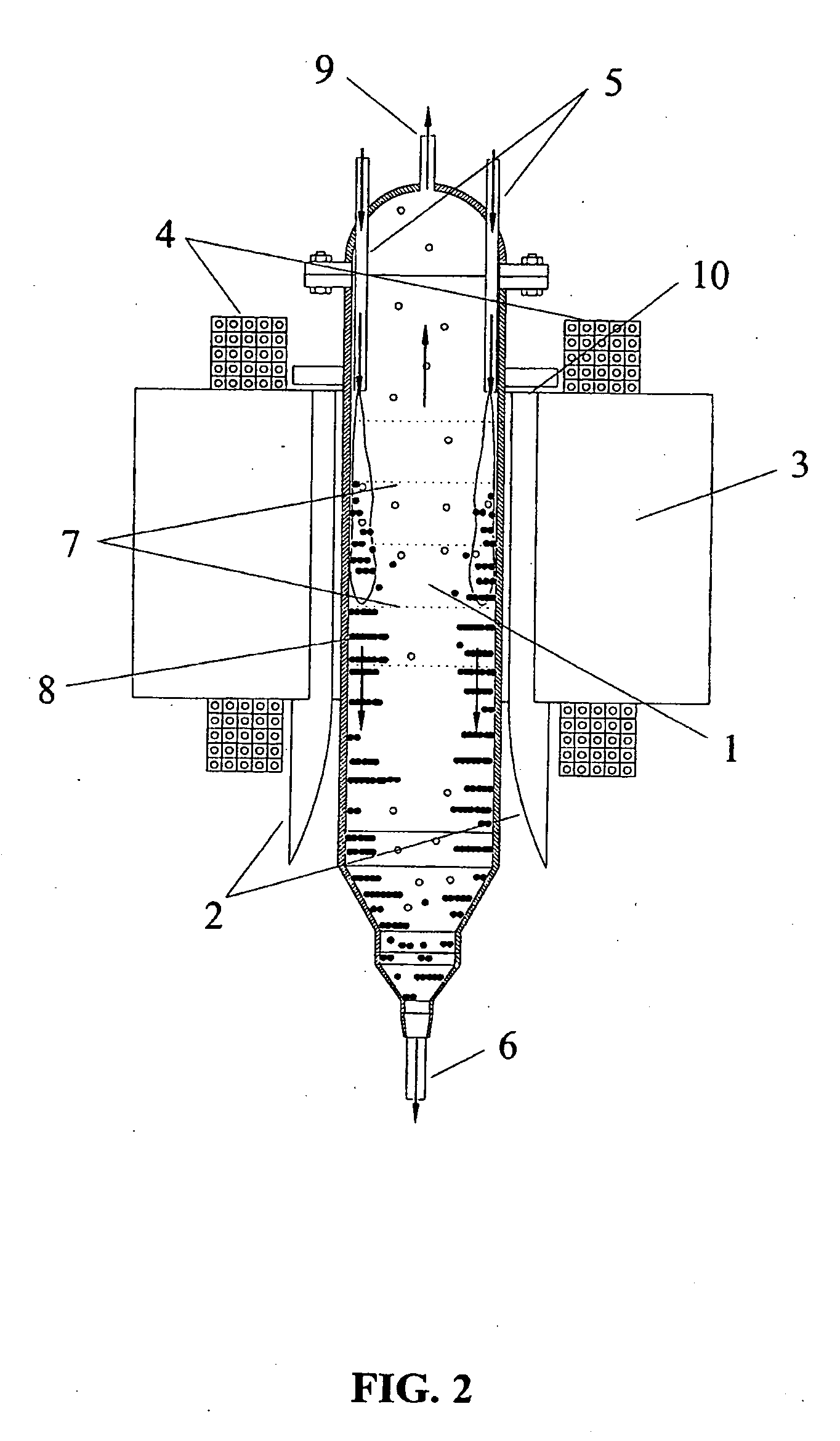
[0052]A slurry containing 21.45 wt. % catalyst was fed at the rate of 17.53 gpm into a 6-inch diameter separation vessel through two sets of down-directed feed lines located across from one another next to the elongated tapered poles of the electromagnet. A vessel with a 6-inch inside diameter was employed. The overall canister length was 21 inches from the top of the dome at the overflow port to the bottom of the straight section which terminated 5 inches below the bottom of the magnet return frame. The volume of the six inch canister is 10 liters. Each set of feed lines consisted of one ¾-inch outer diameter tube and two ½-inch tubes on either side of the ¾-inch inlet. The magnetic field was 2000 gauss. The underflow was withdrawn through a 2-inch pipe (nominal 2.067 inch inner diameter) at a rate of 16.1 gpm and contained 23.33 wt. % ash. The overflow was withdrawn through a ½-inch tube with 0.035-inch wall thickness at the rate of 1.43 gpm and contained 0.35 wt...

example 2

Magnetic Field Effects

[0055]The slurry was fed at an average rate of 11.3 gpm to a 6 inch diameter vessel through two ¾-inch outside diameter down-directed stainless pipes located next to the inside walls of the separation chamber adjacent to the magnet poles as described above. The pipe outlets open into the separation chamber at an elevation which is 3 inches below the top of the electromagnet return frame. The opening at the chamber overflow was ½-inch tubing; the opening at the underflow was nominally 1-inch pipe. The magnetic field strength was varied from the locked-in field of the electromagnet with no current in the energizing coils up to 2200 gauss. Valves were used to maintain a recycle ratio of approximately 11:12. The ash levels in the feed, underflow, and the overflow were measured. The percentage reduction in ash was calculated as % reduction=[(ash in feed−ash in overflow) / ash in feed]*100.

[0056]Results are given versus the applied magnetic field in Table I.

TABLE IEffe...

example 3

Flow Entrance Effects

[0058]The direction in which the slurry is introduced into the separation vessel is important. This is illustrated with measurements made using a 2-inch diameter separation vessel and shown in Table II. All measurements were made at 1000 gauss magnetic field strength.

TABLE IIEffects of Flow Entry DirectionOverflowUnderflowFeedFlowFlowFlowAshRateAshRateAshRateAshRecycleReduction(gpm)(wt %)(gpm)(wt %)(gpm)(wt %)Ratio(wt %)Tangential0.0120.970.17421.380.1920.0314.195.1Tangential0.0060.940.18219.870.1919.2630.395.1Down-Directed0.0410.940.25822.180.3019.306.495.2Down-Directed0.0400.860.31420.720.3518.488.095.4

[0059]Two flow configurations are shown, tangential and down-directed. In the tangential case, one ¼-inch inner diameter entry port is employed. It is located 3 inches above the bottom of the iron return frame of the electromagnet and makes a tangential entry into the separation vessel at 90 degrees with respect to the electromagnet poles. For the two down-direc...


PUM

PropertyMeasurementUnit
temperaturesaaaaaaaaaa
velocityaaaaaaaaaa
densityaaaaaaaaaa

Abstract

An apparatus and method for continuous separation of magnetic particles from non-magnetic fluids including particular rods, magnetic fields and flow arrangements.

Description

STATEMENT REGARDING FEDERALLY SPONSORED RESEARCH[0001]This invention was made with Government support under Grant DE-FG02-00ER83008, awarded by the U.S. Department of Energy. The Government has certain rights in this invention.BACKGROUND OF THE INVENTION[0002]1. Field of the Invention[0003]This invention relates to the art of continuous separation of magnetic particles from a non-magnetic fluid; more specifically it relates to the continuous separation of such types as they pass through a uniform applied magnetic field; and more specifically it relates to the continuous separation of sub-micron size magnetic particles from viscous flows such as the continuous separation of magnetic catalysts from Fischer-Tropsch wax at operating temperature and pressure or separation of particles of wear from transformer oil or spent engine oil and other non-magnetic hydrophobic or hydrophilic liquids.[0004]2. Description of Related Art[0005]U.S. Pat. No. 4,605,678 describes the application of high ...

Claims


Application Information

Patent Timeline
Patent Type & Authority Applications(United States)
IPC IPC(8): B03C1/30B03C1/02
CPCB03C1/0335B03C2201/22B03C1/288
Inventor ODER, ROBIN R.JAMISON, RUSSELL E.
Owner RES USA LLC
Why Eureka
Try Eureka