Electronic control for pool pump

a technology of electronic control and pool pump, which is applied in the direction of pump control, piston pump, non-positive displacement fluid engine, etc., can solve the problems of unnecessarily running the pump, wasting energy and money, and consuming a lot of resources

Inactive Publication Date: 2005-11-24
ALLEN STEPHEN D
View PDF4 Cites 66 Cited by
  • Summary
  • Abstract
  • Description
  • Claims
  • Application Information

AI Technical Summary

Benefits of technology

[0009] The device comprises a data input means, a display, memory, and a controller. It may also include a manual override to allow the user to turn the pump on at any time. The device is connected to the pump motor. The device is connected to a power supply and may also include a battery back-up in the event of a power outage. To prevent the pool from freezing, the system may also include an air temperature sensor that triggers pump operation when the ambient air is below a given temperature.

Problems solved by technology

However, some households maintain the same run time for the pool pump throughout the year, thus wasting energy and money.
Often systems comprise two pumps resulting in an expenditure of about $82 per month.
While some consumers adjust the run time of their constant-duty timer in the winter, and again in the spring, many forget to adjust the run time, resulting in running the pump unnecessarily.
Furthermore, some days during the winter months can be warmer than expected resulting in the pool pump being run for an insufficient duration allowing bacteria to proliferate.
While the pool recirculation control system of U.S. Pat. No. 6,079,950 reduces the run time of the pool filter and pump in accordance with water temperature, the requirement of multiple temperature sensors and multiple timing circuits results in fairly complex system that is costly to produce and purchase and difficult to install.

Method used


Image

  • Electronic control for pool pump
  • Electronic control for pool pump
  • Electronic control for pool pump

Examples


Embodiment Construction

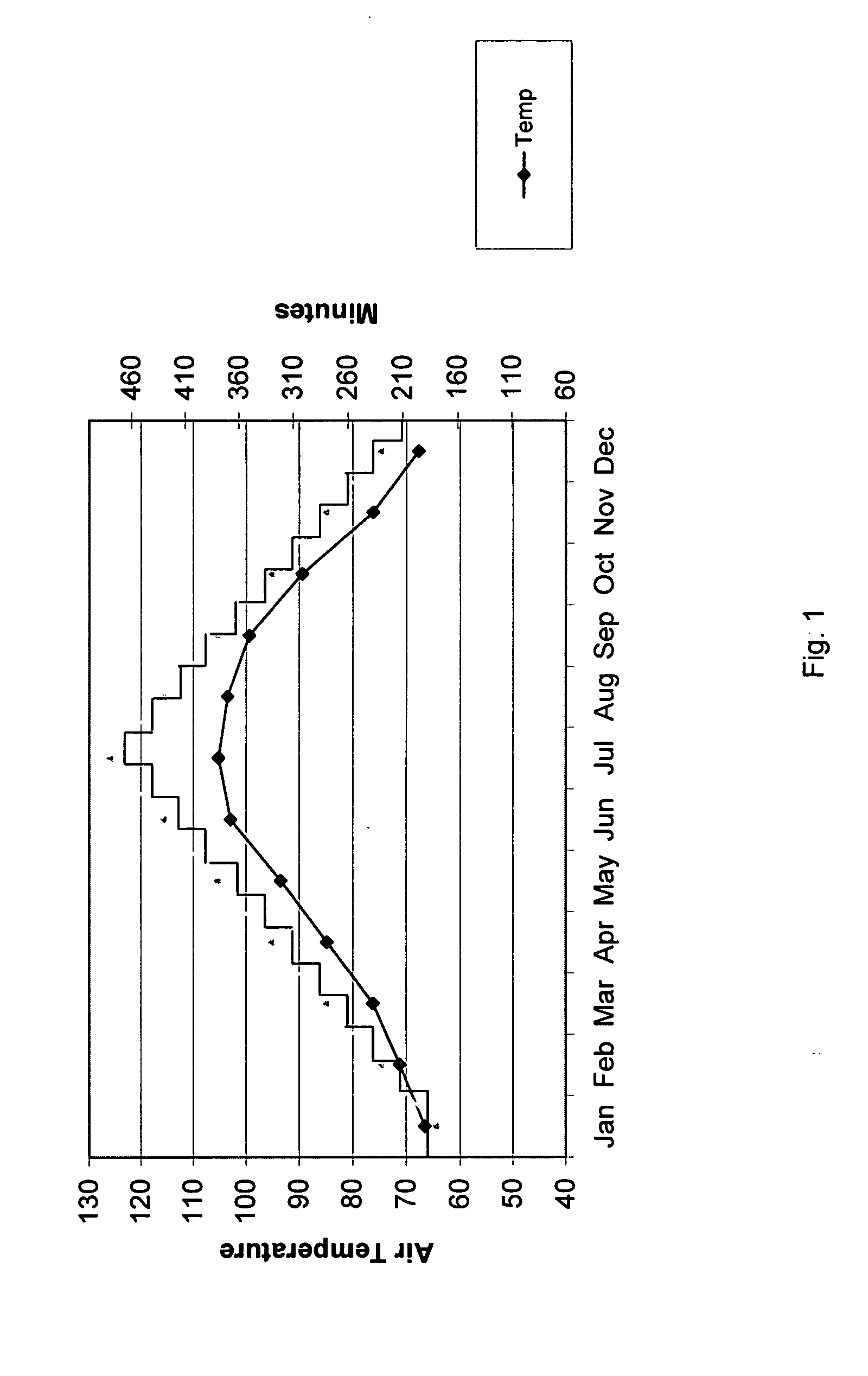
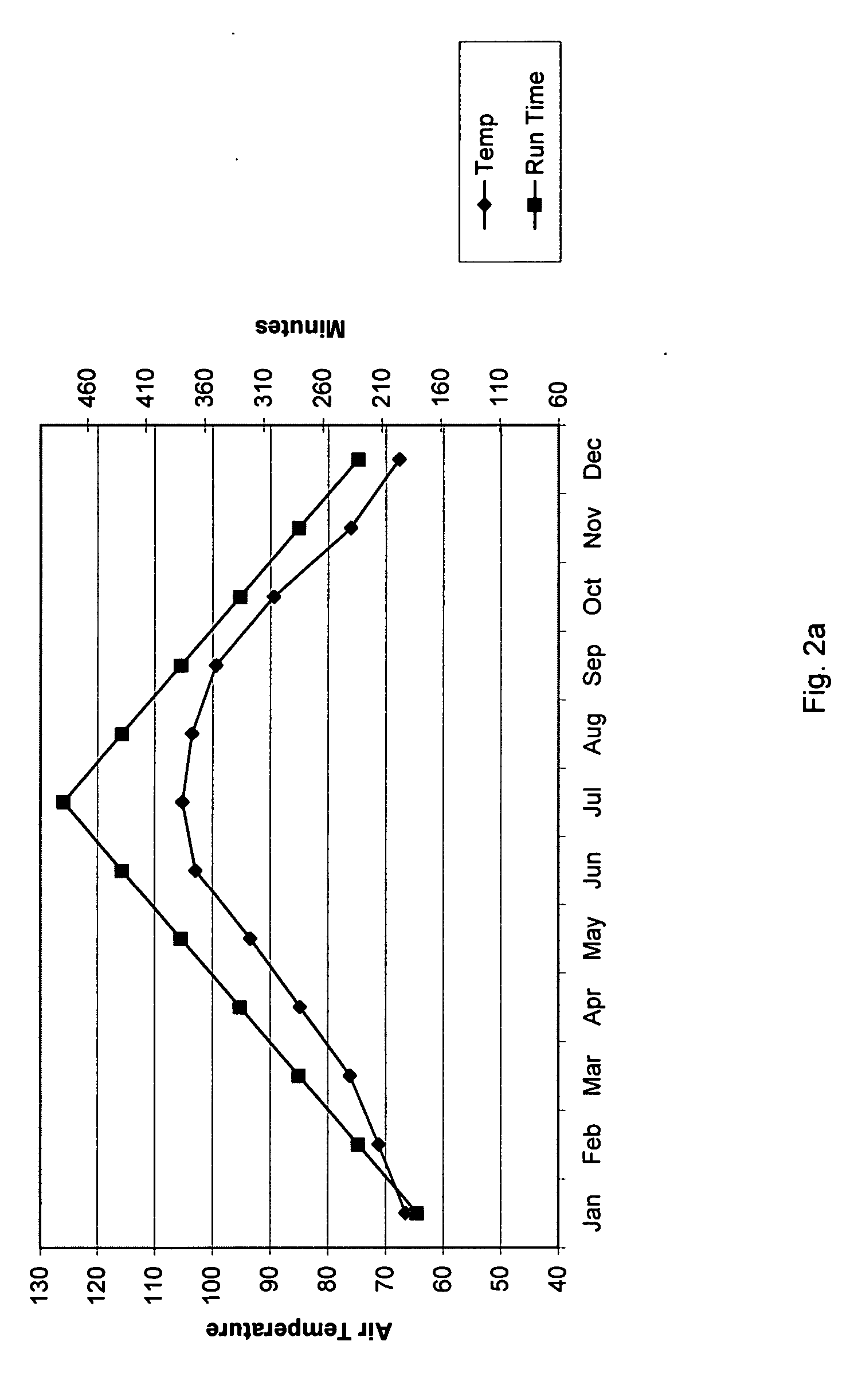
[0017] Air temperatures are generally cooler in the winter and warmer in the summer, although the variance between the minimum and maximum temperatures may vary, depending on the locale. FIG. 1 illustrates a curve 7 of the historical average air temperature for Phoenix, Ariz., where the x-axis is the date and the left y-axis is the air temperature in degrees Fahrenheit. FIG. 1 also illustrates a preferred curve 8 of pool pump run times throughout the year. The right y-axis shows run times in minutes.

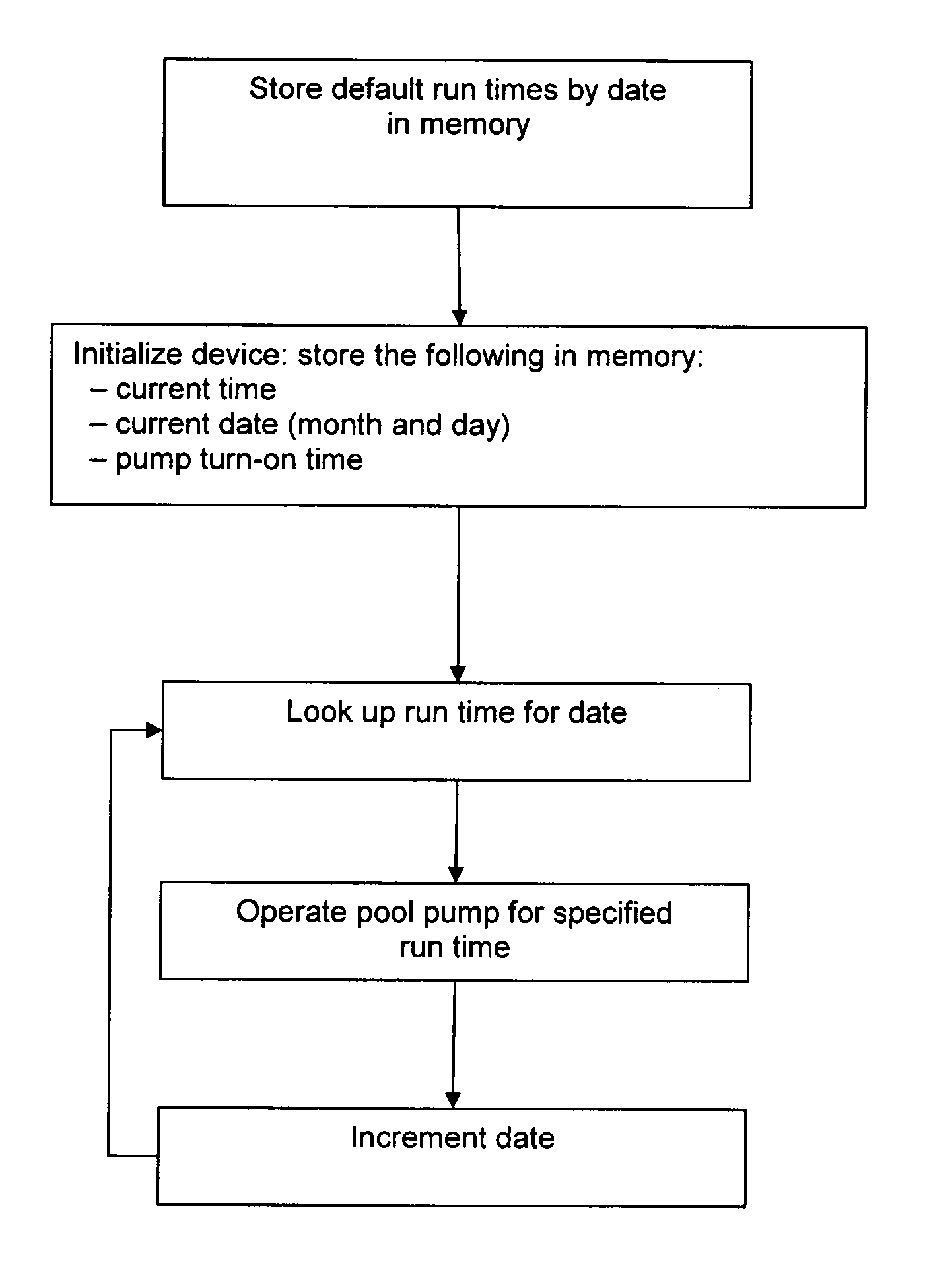
[0018] The present invention is an electronic pool pump timer that controls the run time of the pump for a period of time each day depending on the date to optimize the efficiency of the pump and thereby reduce energy expenditures. To maximize efficiency, the run time curve takes into account the factors that affect the amount of time the pump needs to be run to maintain optimal water quality, such as air temperature, number of bathers (and the degree to which they are slathered in suns...


PUM


Abstract

An electronic pool pump timer that controls the run time of the pump for a period of time each day depending on the date. In the preferred embodiment, the user enters the historical daily maximum and minimum pump run times for the specific pool and the system calculates the required time the pump will run on a given day. The customized run time is thus calculated as a function of the date and the minimum and maximum run times for a given pool. The system then self-adjusts the run time each day as necessary. The device comprises a data input means, a display, memory, and a controller. It may also include a manual override to allow the user to turn the pump on at any time. The device is connected to the pump motor. The device is connected to a power supply and may also include a battery back-up in the event of a power outage. To prevent the pool from freezing, the system may also include an air temperature sensor that triggers pump operation when the ambient air is below a given temperature.

Description

CROSS-REFERENCE TO RELATED APPLICATIONS [0001] This application claims the benefit of co-pending U.S. Provisional Application No. 60 / 573,404 filed May 21, 2004.FIELD OF THE INVENTION [0002] The invention relates to electronic control for a pool pump. In particular, the invention relates to a method and apparatus for electronically controlling the operating time of a pool pump. BACKGROUND TO THE INVENTION [0003] Conventional swimming pools and spas include a water recirculation system comprising a pump and a filter for filtering particles and debris from the pool or spa water. The water is also usually chemically treated to kill bacteria in the water. The rate of bacteria growth in the water is a function of, among other factors, water temperature, and therefore at lower temperatures the pump and pool filter can be run for a shorter time than is required at higher temperatures. However, some households maintain the same run time for the pool pump throughout the year, thus wasting ene...

Claims


Application Information

Patent Timeline
Patent Type & Authority Applications(United States)
IPC IPC(8): F04B17/00F04B49/00F04D15/00
CPCF04D15/00
Inventor ALLEN, STEVEN D.
Owner ALLEN STEPHEN D
Why Eureka
Try Eureka