
Erosion resistant anti-icing coatings

a technology of anti-icing coatings and anti-ice, applied in the field of coatings, can solve the problems of affecting the aerodynamic performance of airfoils such as wings, fan blades, unanticipated loads on components, and ice build-up on aircraft and gas turbine engine structures, and achieve the effect of preventing ice build-up

Inactive Publication Date: 2006-12-14
UNITED TECH CORP
View PDF19 Cites 62 Cited by
  • Summary
  • Abstract
  • Description
  • Claims
  • Application Information

AI Technical Summary

Benefits of technology

[0005] The above-identified shortcomings of existing icephobic coatings are overcome by embodiments of the present invention, which relates to improved icephobic coatings. Liquid and / or solid anti-icing fillers and / or oils are combined with erosion resistant silicone and / or fluorocarbon elastomeric materials to create the erosion resistant icephobic coatings of this invention. These coatings may have ice adhesion strengths of less than about 200 kPa and may be utilized to prevent ice build-up on various components, such as, but not limited to, gas turbine engine components, aircraft components, watercrafts (i.e., boats and ships), power lines, telecommunication lines, etc.

Problems solved by technology

Ice build-up on aircraft and gas turbine engine structures has been a longstanding problem in the aerospace community.
The physical presence of ice can adversely impact the aerodynamic performance of airfoils such as wings, fan blades, inlet guide vanes, fan exit guide vanes, etc.
Additionally, the added weight of ice build-up can place unanticipated loads on components and, in extreme cases, may even exceed the capability of such components.
Furthermore, the ice build-up can shed, which may cause severe damage to an aircraft or engine.
Such systems have many disadvantages: they are complex, they add significant weight to the engine, they require complicated thermal management systems, they lead to decreased engine efficiency due to the lost core airflow, and they often require costly materials or limit the materials that can be used for components due to the high de-icing temperatures that are utilized.
Unprotected thermoset or thermoplastic materials typically have poor erosion resistance, and adding solid or liquid fillers further decreases their erosion resistance.
This is undesirable because the engine and aircraft components that most need ice build-up protection are positioned in severely erosive environments.

Method used


Image

  • Erosion resistant anti-icing coatings

Examples


examples

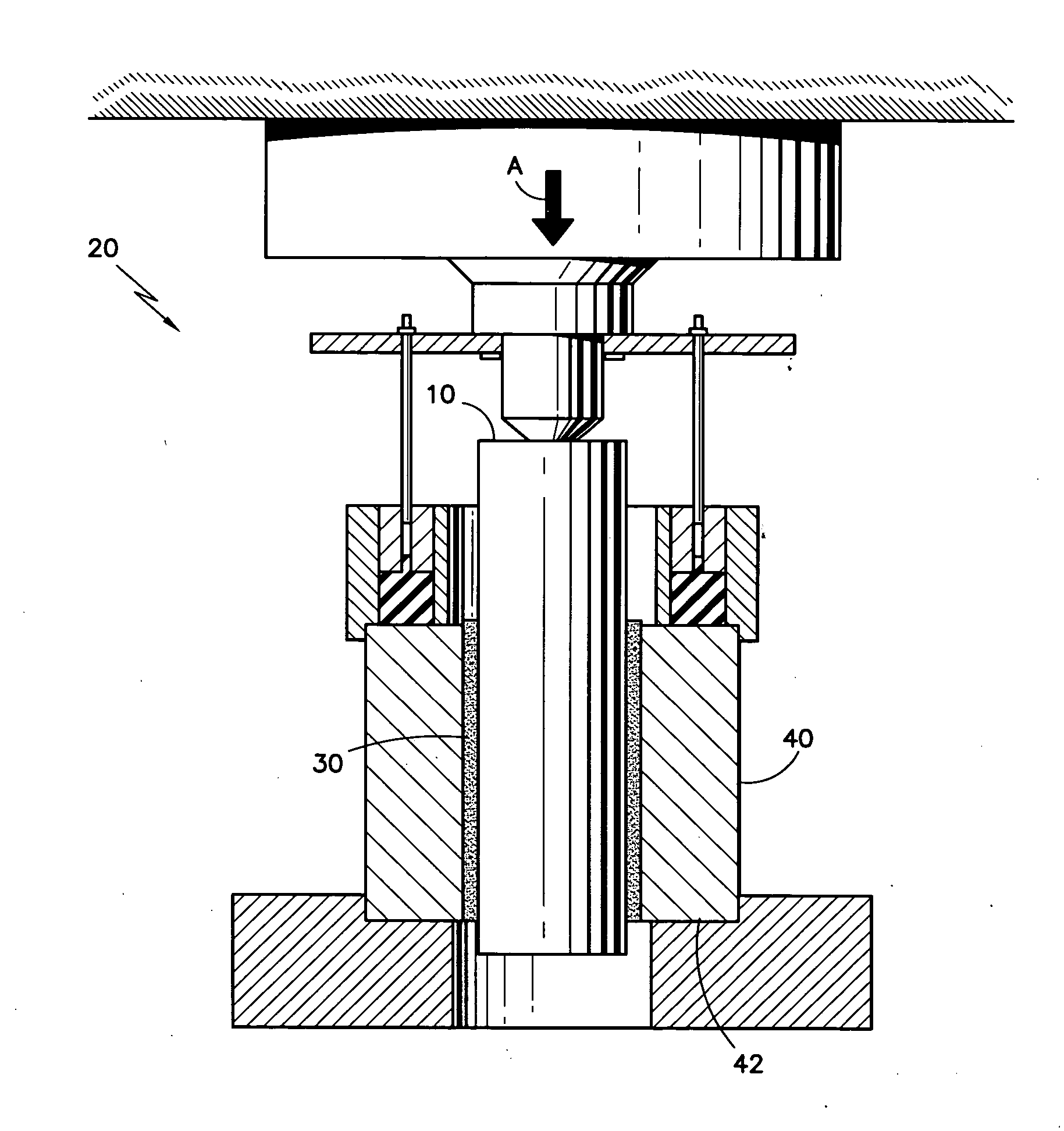
[0021] Various icephobic coatings of this invention were prepared and tested for their respective ice adhesion strengths by coating various aluminum pins with a layer of an exemplary icephobic coating. Each coated pin 10 was positioned in a zero degree cone test apparatus 20 as shown in the FIGURE, where a layer of ice 30 about 10 ±2 mil thick was then grown on each coated pin 10 in the annular gap between the coated pin 10 and the mold 40. The ice 30 was grown by holding the apparatus 20 at a temperature of about −10±10° F. for about 6±+hours. Thereafter, the ice adhesion strength on each coated pin 10 was determined quantitatively via a pin shear test. The pin shear test involved constraining the mold at its base 42 while the pin was loaded axially in the direction of arrow A. This put the ice 30 into shear, and allowed the load at which the ice de-bonded from each coated pin 10 to be determined.

[0022] Various fluorocarbon elastomeric coatings were evaluated. The base fluorocarbo...


PUM

PropertyMeasurementUnit
molecular weightaaaaaaaaaa
weight percentaaaaaaaaaa
temperaturesaaaaaaaaaa

Abstract

Liquid and / or solid anti-icing fillers and / or oils are combined with erosion resistant silicone and / or fluorocarbon elastomeric materials to create erosion resistant anti-icing coatings. These coatings may be utilized to prevent ice build-up on various gas turbine engine components, aircraft components, watercrafts (i.e., boats and ships), power lines, telecommunication lines, etc.

Description

FIELD OF THE INVENTION [0001] The present invention relates generally to coatings, and more specifically, to erosion resistant anti-icing coatings for use on various components. BACKGROUND OF THE INVENTION [0002] Ice build-up on aircraft and gas turbine engine structures has been a longstanding problem in the aerospace community. The physical presence of ice can adversely impact the aerodynamic performance of airfoils such as wings, fan blades, inlet guide vanes, fan exit guide vanes, etc. Additionally, the added weight of ice build-up can place unanticipated loads on components and, in extreme cases, may even exceed the capability of such components. Furthermore, the ice build-up can shed, which may cause severe damage to an aircraft or engine. [0003] Anti-icing systems have been developed to prevent ice build-up on various aircraft components, such as those near the inlet of the engine. Many traditional systems utilize high temperature air from within the core of the engine, which...

Claims


Application Information

Patent Timeline
Patent Type & Authority Applications(United States)
IPC IPC(8): C09K3/18C08L27/00C08L83/04
CPCC09D183/04C09D127/18C08L71/02C08L2666/14C08L2666/02C08L2666/54C08L83/00C09D127/12C09D5/08
Inventor PUTNAM, JOHN W.
Owner UNITED TECH CORP
Learn More