System and method for providing multi-dimensional touch input vector

a multi-dimensional touch input and input vector technology, applied in the field of multi-dimensional touch input vector systems, can solve the problems of inability to detect multiple fingers or objects on the surface, touch panel may stop working, traditional touch panel, etc., and achieve the effect of reducing energy waste in other directions and more energy to be focused

Active Publication Date: 2012-04-26
PQ LABS INC
View PDF5 Cites 26 Cited by
  • Summary
  • Abstract
  • Description
  • Claims
  • Application Information

AI Technical Summary

Benefits of technology

[0022]According to one embodiment, the light transmitter comprises a LED semiconductor die and a lens wherein said lens has a wider x-axis view angle than y-axis view angle. This structure allows more energy to be focused and directed towards the light sensor array and reduces energy waste on other directions.

Problems solved by technology

Traditional touch panels, although widely used, is unable to detect multiple fingers or objects on a surface.
If two or more fingers are simultaneously touched, the touch panel may stop working or it may report only one of the touch positions or an inaccurate phantom touch position.
However, at that time, computer users were still limited to programmers and trained staffs because users had to remember all the command and parameters in order to interact with computers.
However, unlike interactions in our real world, WIMP is limited to single point inputting device (e.g. the user can use mouse to point to only a single location at one time).
This limitation results in serious inefficiency.
Imagine if we have only one finger instead of ten in our everyday life, the life would be very difficult for us.
In addition, WIMP is limited to single user, multi-user operation is not possible because only one mouse / pointing device is available system wide.
The problem associated with light beam matrix touch screen is that it cannot accurately detect multiple touch positions simultaneously.

Method used


Image

  • System and method for providing multi-dimensional touch input vector
  • System and method for providing multi-dimensional touch input vector
  • System and method for providing multi-dimensional touch input vector

Examples


first embodiment

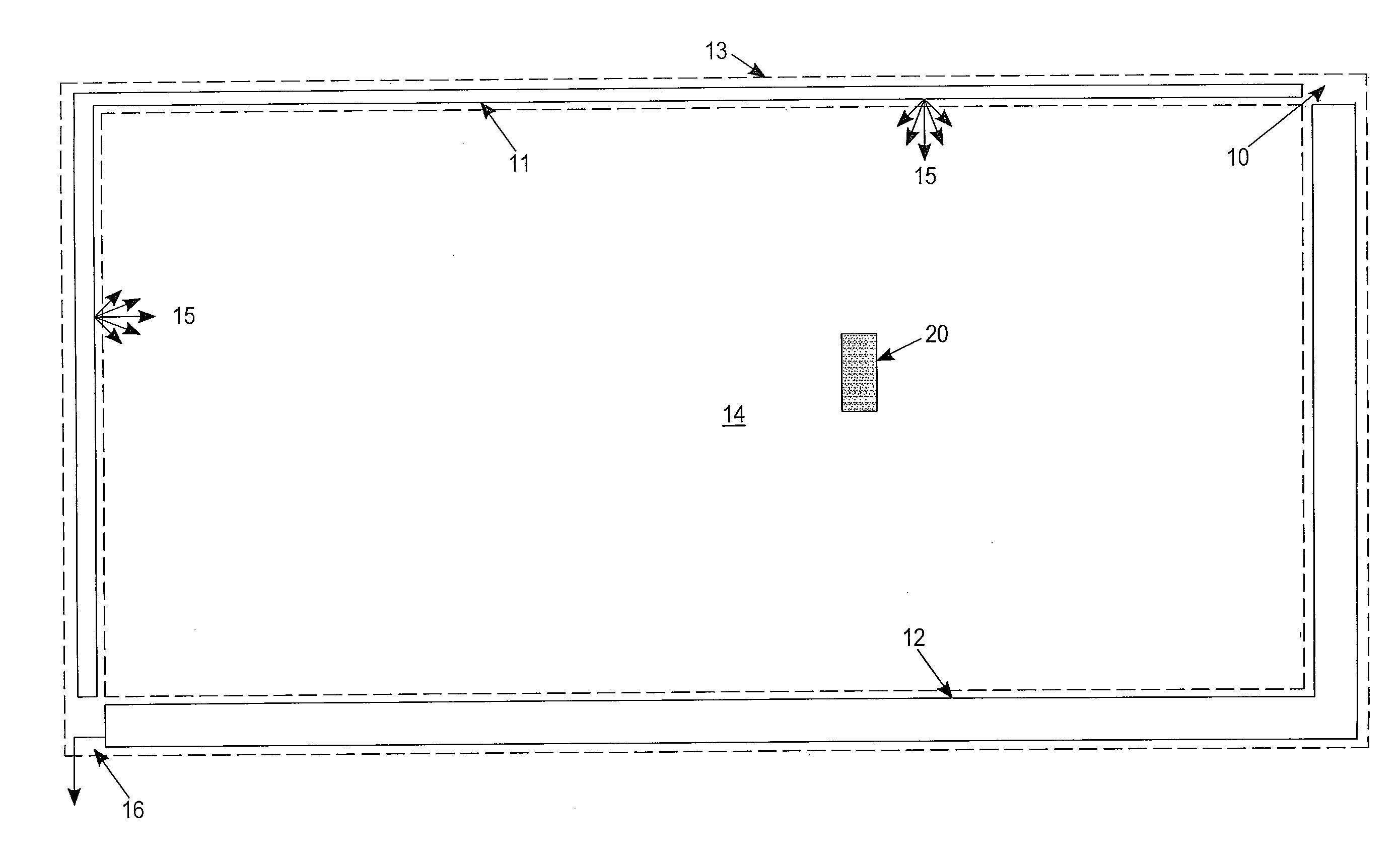
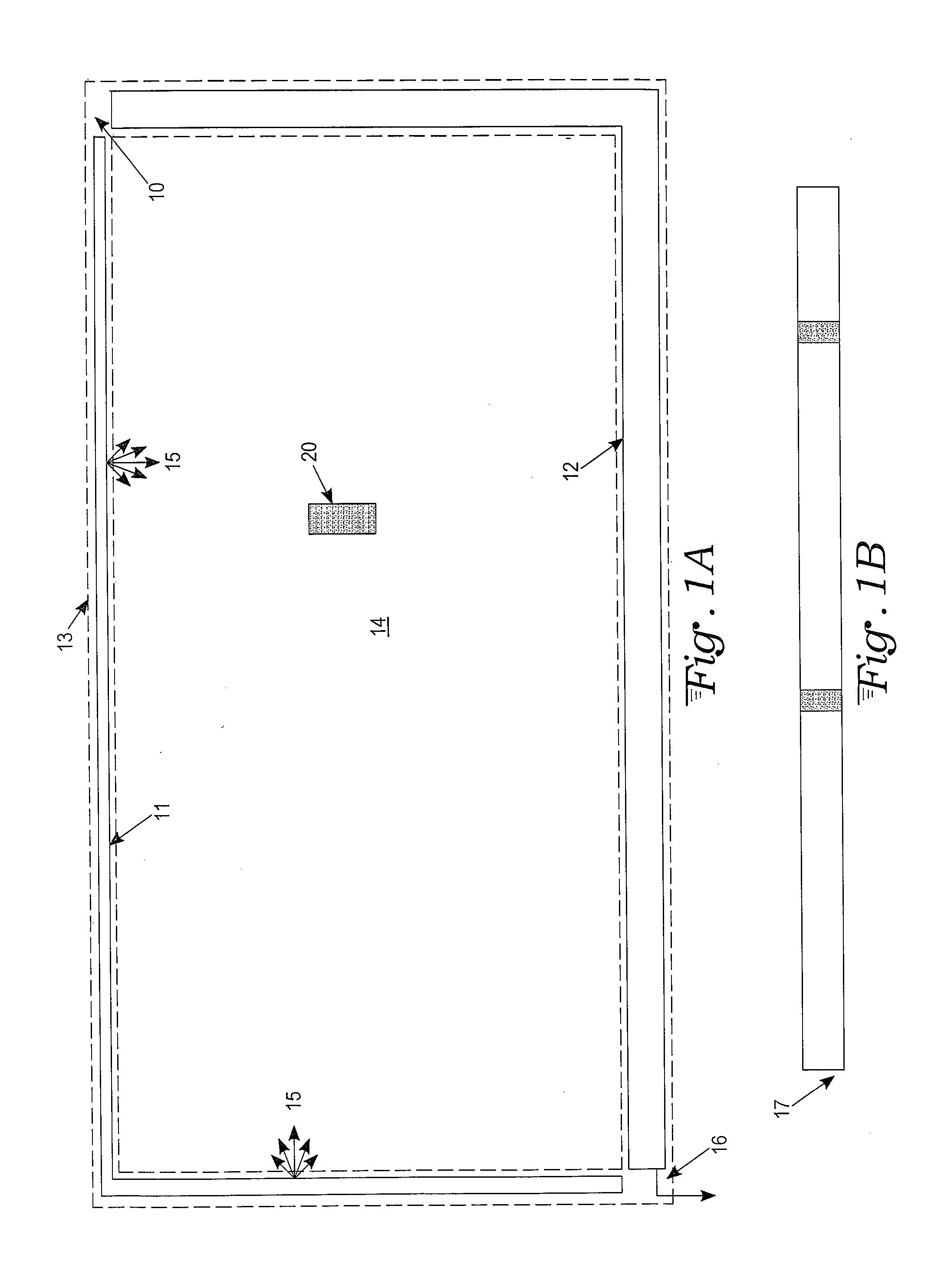
[0030]FIGS. 1A-1B illustrates a touch panel 13 in accord with the present invention, the touch panel in this case having one light transmitter 11 and one light sensor 12. A touch object T020 is located within the touch region W 14. The light transmitter 11 and light sensor 12 are assembled and fastened inside the bezel 10 of the touch panel 13. The light transmitter 11 is in L-shape. Light 15 is evenly emitted along the inner edge of the L-shape transmitter and spreads towards different parts of the touch region W 14. The L-shape light transmitter can be made of a single light fiber or a LED backlight structure. The L-shape light sensor is placed on the opposite sides of the light transmitter to detect the intensity of incoming light energy. The L-shape light sensor outputs a series of analog or digital signals 16 to a processing unit, which produces a one-dimensional light intensity image 17 representing different light intensity detected along different part of the L-shape sensor....

second embodiment

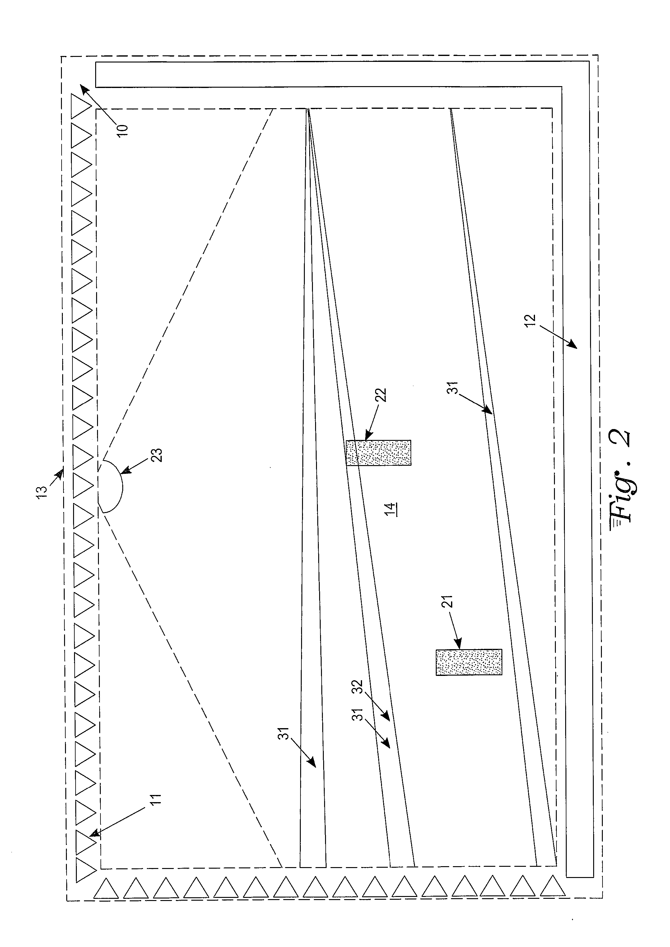
[0031]FIG. 2 illustrates a touch panel 13 in accord with the present invention, the touch panel in this case having a plurality of light transmitters 11 and one light sensor 12. Two touch objects 21, 22 are seen to be present within the touch region W 14. The light transmitters 11 can be a plurality of infrared LEDs. Each LED contains a semiconductor die and an optical lens. The optical lens is associated with a view angle 23 property that allows most infrared light energy to spread within the area defined by the view angle 23. The light sensor 12 is of L-shape and can be made of a customized contact image sensor unit. The light path 31 is defined according to the size, location and optical structure of the light transmitter and light sensor. In the configuration illustrated in FIG. 2, each light path 31 can be defined as a triangle connecting between the infrared LED and the pixel located on the contact image sensor. For each light path, the sensor detects the light intensity. The ...

third embodiment

[0032]FIG. 3 illustrates a touch panel 13 in accord with the present invention, the touch panel in this case having a plurality of light transmitters 11 on one side of the touch panel 13 and a plurality of light sensors 12 on the opposite side of the touch panel 13. The other two sides of the touch panel 13 are empty. This particular configuration is best for extremely long touch panel or touch wall applications, where the left and right side of the touch panel are so far apart (e.g. several meters long) that light energy detected on the left or right edge is very weak. This particular configuration is also best for low cost implementation of this invention because fewer components are required. In FIG. 3, there are two touch objects 21, 22 within the touch region W 14. The light transmitters 11 can be a plurality of infrared LEDs. The light sensors 12 can be a plurality of phototransistor sensors or photodiode sensors. Each of the light sensors can detect the light intensity measur...


PUM


Abstract

A touch panel method and system detects one or more touch objects placed on a surface of a touch panel and assigns consistent ID, position, size and convex contour to each touch object. The method and system allows multiple simultaneous touch objects on the touch panel to be distinguished. The touch panel includes on its periphery at least one light transmitter and at least one light sensor, each positioned around at least a portion of a perimeter of the touch panel. A processor in communication with the at least one light sensor acquires light intensity data from the sensor(s), wherein any one or more touch objects placed within a touch detectable region of the panel interrupts at least a subset of light paths between transmitter and sensor. Based on the interrupted light paths, the processor generates a touch input vector (assigned ID and spatial properties) that represents the placement of each touch object on the touch panel.

Description

TECHNICAL FIELD[0001]The present invention relates to techniques for enabling feature rich sensing of id, position, size and the convex contour of one or multiple touch objects placed on the surface of a touch panel.BACKGROUND ART[0002]A touch panel is a type of user interface device that may be attached to a surface of a display device or a projection surface. Traditional touch panels, although widely used, is unable to detect multiple fingers or objects on a surface. If two or more fingers are simultaneously touched, the touch panel may stop working or it may report only one of the touch positions or an inaccurate phantom touch position.[0003]The interface of controlling a machine using multiple fingers has a long history even before the computer was invented (e.g. piano, control panel, DJ mixer, etc). As computers become available to more populations and become increasing powerful, the human computer interface has evolved more and more natural to the users representing real inter...

Claims


Application Information

Patent Timeline
Patent Type & Authority Applications(United States)
IPC IPC(8): G06F3/041
CPCG06F3/0428G06F3/0308G06F2203/04104G06F3/0421
Inventor LU, FEI
Owner PQ LABS INC
Why Eureka
Try Eureka