[0025]A primary objective of the present invention is to provide systems, methods and devices for a simple to implement, multifunctional, factory produced, self-contained (aside from sources / sinks / storage and
piping), fully integrated, automated heating and cooling system that incorporates methods and devices required for a building HVAC system that includes, but is not limited to, automated real time and future
energy requirement projections for a building, or group of buildings, to more efficiently meet
building energy requirements. This
energy management capability uses devices having the automated functionality of
energy sensing,
load forecasting, harvesting, storage, management and transportation to increase the efficiency of building heating and cooling systems while simplifying the design and construction of the
building energy system. This system requires much less custom
engineering, less on-site construction time and complexity than currently available alternatives.
[0027]A third objective of the present invention is to provide systems, methods and devices to efficiently transport energy from where it is produced where it is needed without introducing a lot of complexity to the construction process. This includes set up screens for the system that allow it to be easily customized to the implementation.
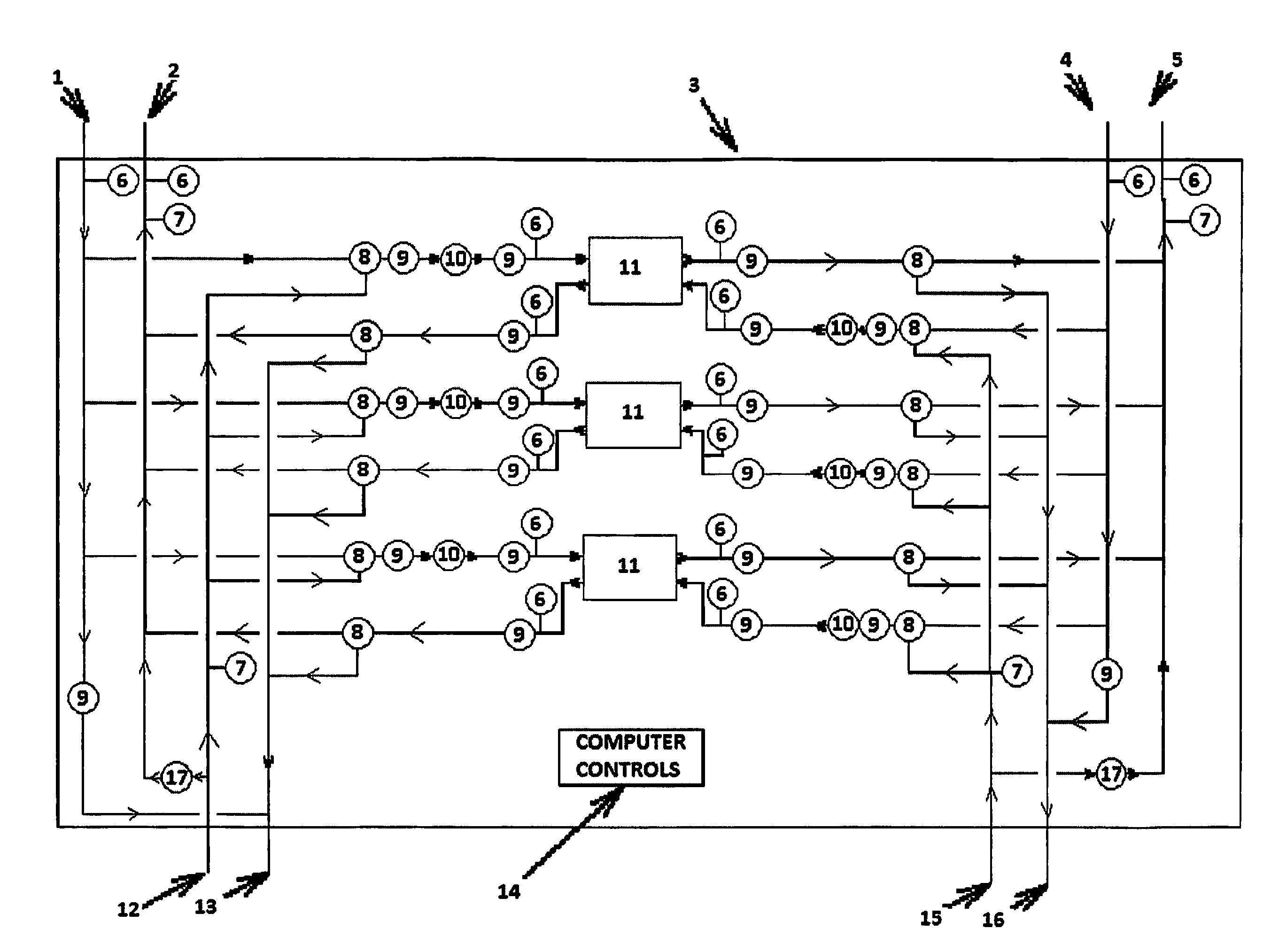
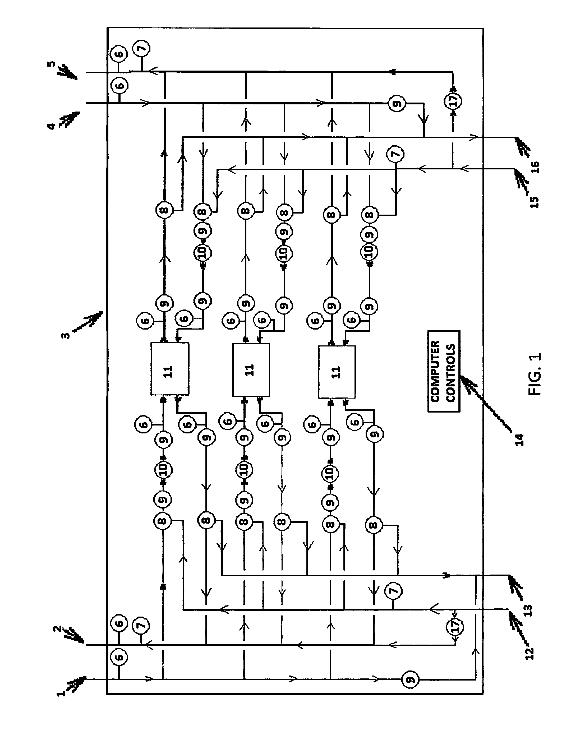
[0028]A fourth objective of the present invention is to provide systems, methods and devices for a mechanical-controlled and computer-controlled fluid mix determination and temperature-control systems and
interconnectivity functionality including methods and devices for controlling the transportation and exchange of energy. This functionality facilitates the selection,
interconnection and switching required for the mixing and use of common and uncommon sources of energy, so as to use that energy more efficiently. Said functionality also facilitates the selection, switching, and
interconnection of the common and uncommon devices including solar collectors, geothermal,
energy recovery units,
fuel cells and other sources of energy required to use said sources and to allow the sources to be mixed to increase the efficiency of the
energy harvesting, to use multiple inputs connected to multiple outputs, and to provide significant increase in energy
synergy.
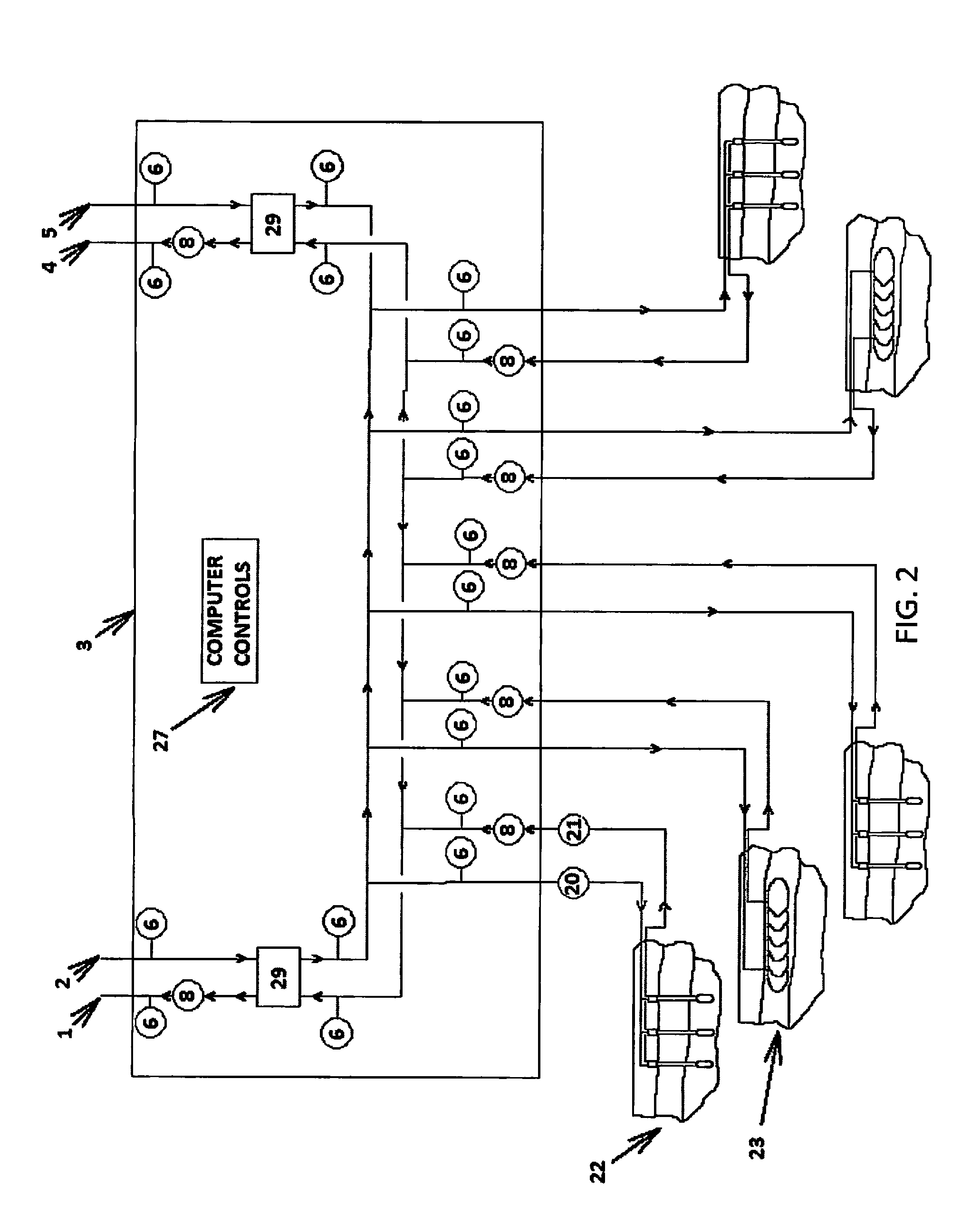
[0029]A fifth objective of the present invention is to provide fully integrated and automated systems, methods and devices for providing a next generation geothermal
heat exchanger that employs the ability to mix different types of loops in a single implementation, to charge some of the loops with
thermal energy while others are being simultaneously discharged and to store energy in the loops and that incorporates the intelligence and controls of the system into a standardized product that can be attached to any form of
closed loop geothermal heat pump system. This geothermal
heat exchanger can be used as an optional addition to the energy
chassis device (i.e. the complete central heating, cooling and
energy management system that includes the computer,
software,
refrigerant-based
heat transfer device such as a
heat pump, circulating pumps and variable speed drives, interconnecting
piping, sensors and control devices, plus the electrical connections, inverters, switches, fuses and wiring and the like required to manage and control the electrical and HVAC system), or in a stand-alone configuration to significantly reduce the custom
engineering, construction time and construction complexity required to implement a geothermal system with equivalent functionality.
[0030]A sixth objective of the present invention is to provide systems, methods and devices for providing a next generation geothermal heat exchanger that uses emerging
computer technology, sensor and control technology, advanced heating and cooling concepts, and the ability to
package the intelligence and control platform into a standardized product for a combination and integration of technology that increases the performance of the geothermal system while maintaining, or reducing, the installed cost of the system.
[0032]An eighth objective of the present invention is to provide systems, methods, and devices for managed and measured short and long-term
thermal energy storage in a
hybrid configuration (i.e. the combination of multiple types of sources / sinks in the same system), utilizing various forms of geothermal heat exchanger configurations in addition to
energy storage within the building fabric (structure) via embedded hydronic
piping that can also be combined with other thermal storage such as
phase change materials /
ice storage,
chilled water storage,
phase change materials / hot
water storage, etc. The invention allows for integration with all
thermal energy storage known in the art, as well as any future energy storage. The use of
thermal energy storage time shifts energy harvested from the environment, so it can be used when the original source is not available (e.g. the sun is down,
waste heat is not being produced, people have left the building, and the like). This allows multiple sources of energy to be merged so that when one source is insufficient, or too expensive to implement to meet the full load requirement, multiple sources can be used to reduce the amount of capital required to build the entire system that makes each source available in a reservoir, so that it may be reliably used according to projected system needs and optimization calculations.

