[0007]The method may further include displaying at least one optimized setting for the at least one cooling provider that results in a reduction in energy usage of the data center while satisfying the cooling requirements of the cooling consumer. The at least one optimized setting may be an airflow setting of the at least one cooling provider. The at least one optimized setting may relate to temperature of a
coolant supplied to the at least one cooling provider. The method may further include adjusting the at least one optimized setting for the at least one cooling provider to reduce energy usage of the data center. Adjusting the at least one optimized setting may include adjusting an airflow setting of the at least one cooling provider. Adjusting the at least one optimized setting may include adjusting temperature of a
coolant supplied to the at least one cooling provider, and may include adjusting an airflow setting of the at least one cooling provider and adjusting temperature of a
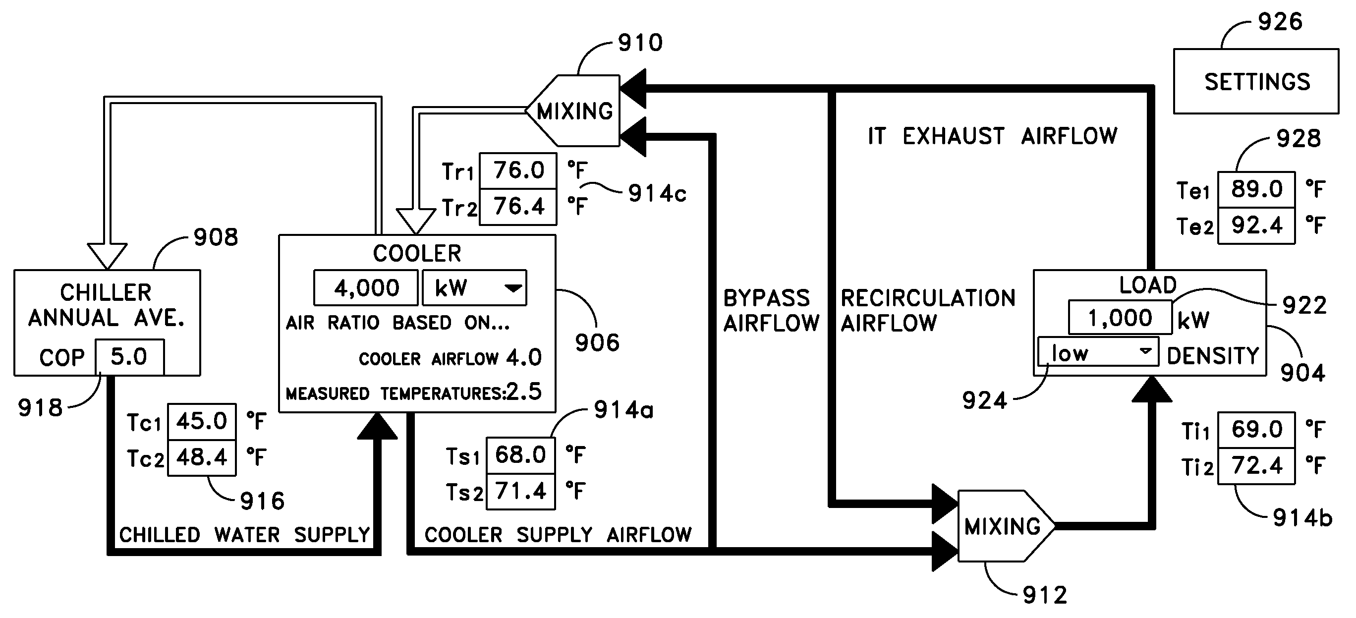
coolant supplied to the at least one cooling provider. The at least one cooling consumer may include a plurality of equipment racks in the data center, and the at least one cooling provider may include a plurality of coolers, and the method may further include creating a model of the data center with the plurality of equipment racks represented by a single equipment rack and the plurality of coolers represented by a single cooler, and determining lumped cooling availability and
power consumption for the single equipment rack, based on characteristics of each of the plurality of equipment racks, and determining lumped
cooling capacity of the single cooler based on characteristics of the plurality of coolers, wherein determining at least one value representative of the effectiveness of the distribution of airflow includes determining at least one value representative of the effectiveness of the distribution of airflow between the single equipment rack and the single cooler. The method may further include providing a
user interface on a computer screen, wherein the
user interface includes user selectable elements to adjust settings for the at least one cooling provider, receiving input from a user to adjust the settings for the at least one cooling provider, and providing an updated value representative of the effectiveness of the distribution of airflow in the data center between the at least one cooling consumer and the at least one cooling provider in real
time based on the input received. The method may further include determining the at least one optimized setting based at least in part on any fractional increase in power due to an increase in fan speed of at least one
server in the data center.
[0009]The controller may be further configured to display on the interface at least one optimized setting for the at least one cooling provider that results in a reduction in energy usage of the data center while meeting the cooling requirements of the at least one cooling consumer, and the at least one optimized setting may be an airflow setting of the at least one cooling provider. The at least one optimized setting may relate to temperature of a coolant supplied to the at least one cooling provider. The controller may be further configured to adjust the at least one optimized setting for the at least one cooling provider to reduce energy usage of the data center, and the controller may be configured to adjust an airflow setting of the at least one cooling provider to reduce energy usage of the data center, and to adjust temperature of a coolant supplied to the at least one cooling provider. The controller may also be configured to adjust an airflow setting of the at least one cooling provider and adjust temperature of a coolant supplied to the at least one cooling provider. The at least one cooling consumer may include a plurality of equipment racks in the data center, and the at least one cooling provider may includes a plurality of coolers, and the controller may be further configured to create and display on the interface a model of the data center with the plurality of equipment racks represented by a single equipment rack and the plurality of coolers represented by a single cooler, and determine lumped cooling availability and
power consumption for the single equipment rack, based on characteristics of each of the plurality of equipment racks, and determine lumped cooling capacity of the single cooler based on characteristics of the plurality of coolers. The controller may be further configured to display on a computer screen of the
user interface graphics that include user selectable elements to adjust settings for the at least one cooling provider, receive input from a user to adjust the settings for the at least one cooling provider, and provide an updated value representative of the effectiveness of the distribution of airflow in the data center between the at least one cooling consumer and the at least one cooling provider in real
time based on the input received. The controller may be configured to determine the at least one optimized setting based at least in part on any fractional increase in power due to an increase in fan speed of at least one
server in the data center.
[0011]The sequences of instruction may include instructions that will cause the processor to display on the interface at least one optimized setting for the at least one cooling provider that results in a reduction in energy usage of the data center while meeting the cooling requirements of the cooling consumer. The at least one optimized setting may be an airflow setting of the at least one cooling provider. The at least one optimized setting may relate to temperature of a coolant supplied to the at least one cooling provider. The sequences of instruction may include instructions that will cause the processor to provide an output to adjust the at least one optimized setting for the at least one cooling provider to reduce energy usage of the data center. The sequences of instruction may include instructions that will cause the processor to provide an output to adjust an airflow setting of the at least one cooling provider to reduce energy usage of the data center. The sequences of instruction may also include instructions that will cause the processor to provide an output to adjust temperature of a coolant supplied to the at least one cooling provider. The sequences of instruction may include instructions that will cause the processor to provide an output to adjust an airflow setting of the at least one cooling provider and adjust temperature of a coolant supplied to the at least one cooling provider. The sequences of instruction may further include instructions that will cause the processor to create and display on the interface a model of a data center with a plurality of equipment racks represented by a single equipment rack and a plurality of coolers represented by a single computer room air conditioner, and determine lumped cooling availability and power consumption for the single equipment rack, based on characteristics of each of the plurality of equipment racks, and determine lumped cooling capacity of the single cooler based on characteristics of the plurality of coolers, and determine at least one value representative of the effectiveness of the distribution of airflow in the data center between the single equipment rack and the single cooler. The sequences of instruction may include instructions that will cause the processor to provide data to the interface to display
graphics that include user selectable elements to adjust settings for the at least one cooling consumer, receive input from a user to adjust the settings for the at least one cooling consumer, and provide an updated value representative of the effectiveness of the distribution of airflow in the data center between the at least one cooling consumer and the at least one cooling provider in real
time based on the input received. The sequences of instruction may include instructions that will cause the processor to determine the at least one optimized setting based at least in part on any fractional increase in power due to an increase in fan speed of at least one
server in the data center.


