Ultrasound profile applied to aerial engine fan/compressor rotor and design method thereof

A compressor rotor, aero-engine technology, applied to engine components, machines/engines, mechanical equipment, etc., can solve problems such as large performance, mutation, deviation, etc.

Inactive Publication Date: 2008-05-21
NANJING UNIV OF AERONAUTICS & ASTRONAUTICS
View PDF1 Cites 16 Cited by
  • Summary
  • Abstract
  • Description
  • Claims
  • Application Information

AI Technical Summary

Problems solved by technology

The surface is composed of straight line segments. When the flow is not in the design state, the wave system will undergo a sudde

Method used


Image

  • Ultrasound profile applied to aerial engine fan/compressor rotor and design method thereof
  • Ultrasound profile applied to aerial engine fan/compressor rotor and design method thereof
  • Ultrasound profile applied to aerial engine fan/compressor rotor and design method thereof

Examples


Embodiment approach

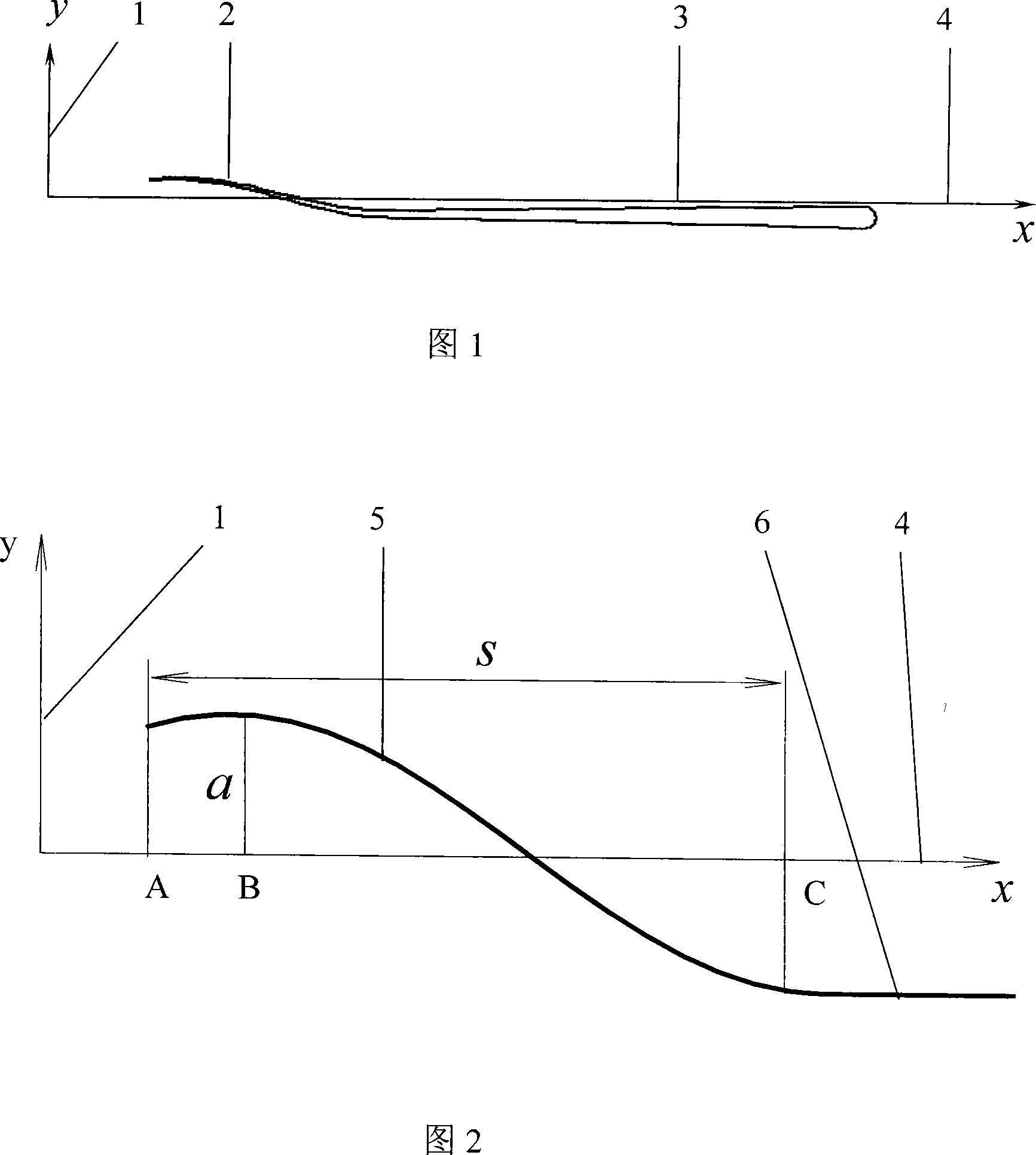
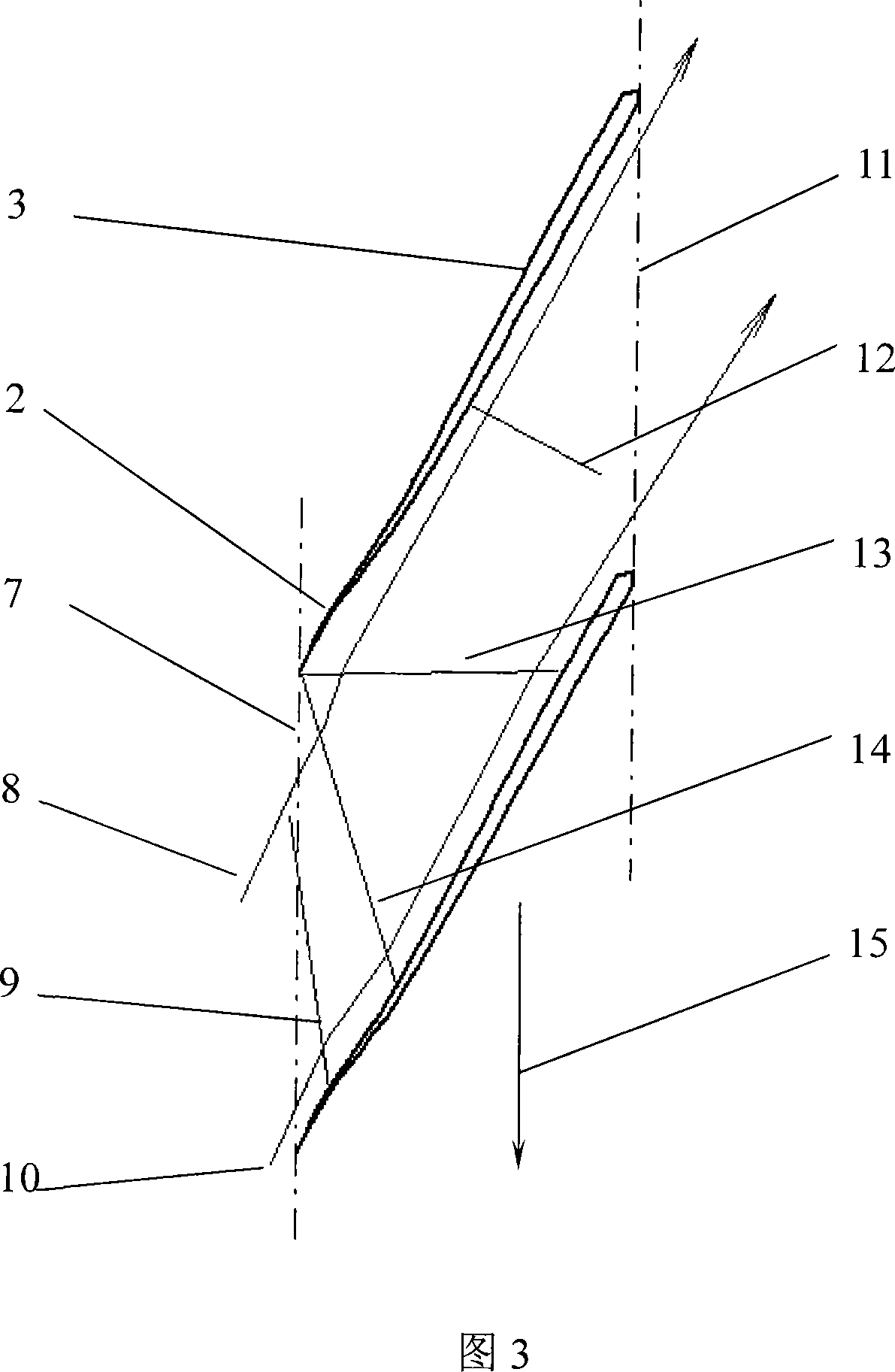
[0028] Determine the velocity triangle at a given blade height according to the torsion design of the supersonic fan / compressor; determine the grid pitch of the blades by the number of blades; determine the length of the blades according to the consistency of the blades; determine the blade shape shown in Figure 1, that is, near the leading edge It is S-shaped, and the rear part is a straight segment blade type (the specific method of determining the blade type will be explained later); the installation angle of the blade is determined by the installation at zero angle of attack. Finally, arrange the obtained airfoils according to the installation angle and grid pitch requirements to form the cascade shown in Figure 3.

[0029] The airfoil shape is determined by superimposing the thickness distribution of the mid-arc. From Fig. 2, the arc in the S-shaped curved section of the airfoil is expressed by a sinusoidal curve, specifically: x=S(q-q1) / (1.5p-q1), y=asin(q). where x is ...


PUM


Abstract

The present invention relates to an ultrasonic blade and a design method applied to aeroengine fans or aerocompressor rotors, pertaining to the art of impeller mechanical technology. The blade is characterized in that the small part of the blade on the front edge is S-shape and the large rear at the rear is flat and the thickness of the blade gradually increased from front to back; the ultrasonic air current flows into a grid formed by the blade, produces an expansion wave in the entrance of the grid, consequently forms an oblique shock wave in the transition from the S-shaped suction surface of the blade to the flat section intersected with the front edge of the adjacent blade, then produces a reflection shock wave and reproduces a local shock wave near the exit of the grid. The design method of the blade includes the following process: the front part is confirmed to be S-shaped and the rear part is divided by a straight medial camber line; the thickness distribution of the blade, which gradually increases from front to back, is confirmed; the surface mold of the blade is confirmed according to the medial camber line and the thickness distribution of the blade. The blade provided by the present invention can effectively reduce the flowing loss, increase the rim power of the rotor and improve the overall pressure ratio.

Description

technical field [0001] The invention relates to an ultrasonic vane profile and a design method applied to an aeroengine fan / compressor rotor, belonging to the technical field of impeller machinery. Background technique [0002] In order to increase the fan / compressor stage pressure ratio and reduce the number of stages, modern aviation turbofan engine fan / compressor designs mostly use rotor inlet relative speed ultrasound and shock wave supercharging. The shock wave itself will generate entropy increase (flow loss); at the same time, the interference between the shock wave and the boundary layer will cause the boundary layer to thicken and even produce local separation. Therefore, when designing ultrasonic or transacoustic rotor blades, it is necessary to carefully organize the shock wave in the rotor channel to reduce the flow loss. [0003] Konig W M, Hennecke D K and Fottner L published in the Journal of Turbomachinery (Volume 11, pages 81-87) titled "Improved Blade Prof...

Claims


Application Information

Patent Timeline
IPC IPC(8): F01D5/14
Inventor 周正贵雷延生
Owner NANJING UNIV OF AERONAUTICS & ASTRONAUTICS
Why Eureka
Try Eureka