Method for designing special wind turbine airfoil profile and special wind turbine airfoil profile

A design method and technology of wind turbines, applied in the direction of wind engines, wind turbine components, mechanical equipment, etc., can solve the problems of limited research work on special airfoils for wind turbines

Inactive Publication Date: 2010-12-22
CHONGQING UNIV
View PDF0 Cites 19 Cited by
  • Summary
  • Abstract
  • Description
  • Claims
  • Application Information

AI Technical Summary

Problems solved by technology

However, with the rapid development of wind turbine technology, it is found that the traditional aviation airfoils cannot well meet the requirements of the specific operating environment of wind turbines. Airfoil series for wi

Method used


Image

  • Method for designing special wind turbine airfoil profile and special wind turbine airfoil profile
  • Method for designing special wind turbine airfoil profile and special wind turbine airfoil profile
  • Method for designing special wind turbine airfoil profile and special wind turbine airfoil profile

Examples


Embodiment 1

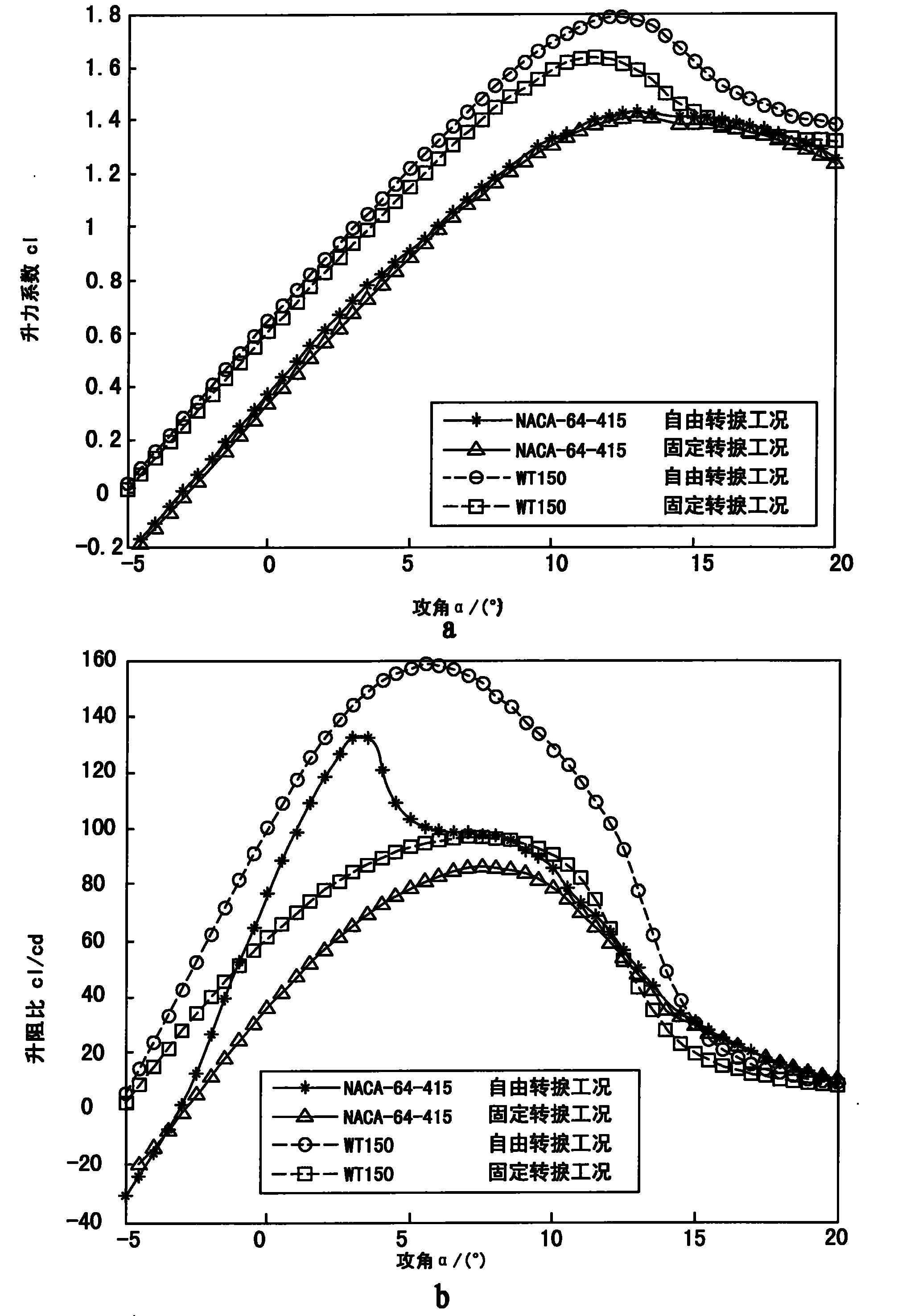
[0109] Such as figure 1 with figure 2 As shown, the special airfoil WT150 for wind turbines is obtained by selecting the thickness constraint of the airfoil thickness of 0.15, which is obtained by optimizing the design method of the special airfoil for wind turbines described in claim 1, and the maximum thickness of the airfoil is located in the chord direction At x / c=0.254, the maximum camber is cam / c=0.037385, and the chord position is x / c=0.443. The following table shows the coefficients of the shape function equation of the airfoil WT150.
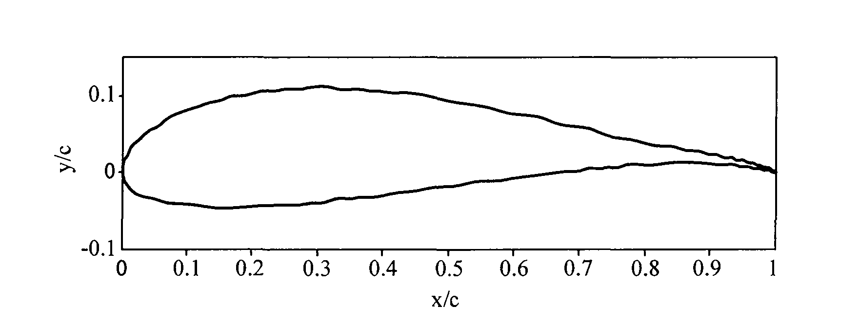
[0110] airfoil

[0111] Use the special analysis software RFOIL 3D airfoil for wind turbine airfoil to conduct detailed aerodynamic characteristics analysis. The analysis results of the airfoil WT150 can be found in figure 2 . It can be seen from the figure that the airfoil WT150 has low roughness sensitivity and is not sensitive to external pollution, foreign object damage and processing; it has a high lift coefficient a...

Embodiment 2

[0113] Such as image 3 with Figure 4 As shown, the special airfoil WT170 for wind turbine is obtained by selecting the thickness constraint of the airfoil thickness as 0.17, which is obtained by optimizing the design method of the special airfoil for wind turbine according to claim 1, and the position of the maximum thickness of the airfoil is in the chord direction At x / c=0.289, the maximum camber is cam / c=0.029445, and the chord position is x / c=0.460. The following table shows the coefficients of the shape function equation of the airfoil WT170.

[0114] Airfoil name

[0115] Use the special analysis software RFOIL 3D airfoil for wind turbine airfoil to analyze the detailed aerodynamic characteristics. The analysis results of the airfoil WT170 are shown in Figure 4 . It can be seen from the figure that the airfoil WT170 has low roughness sensitivity and is not sensitive to external pollution, foreign object damage and processing; it has a high lift coefficien...

Embodiment 3

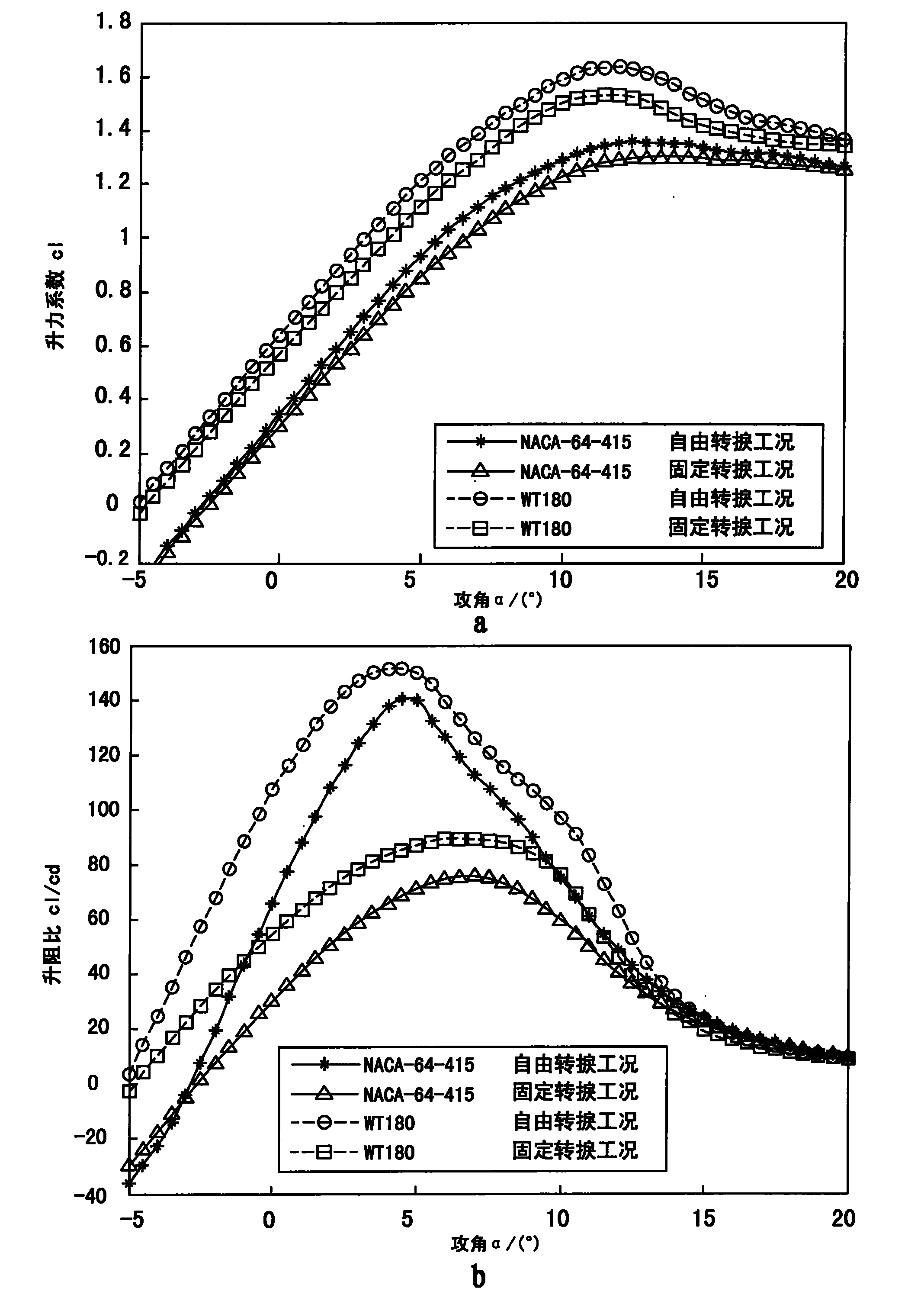
[0117] Such as Figure 5 with Image 6 As shown, the special airfoil WT180 for wind turbines is obtained by selecting the thickness constraint of the airfoil thickness of 0.18, which is obtained by optimizing the design method of the special airfoil for wind turbines described in claim 1, and the maximum thickness of the airfoil is in the chord direction At x / c=0.289, the maximum camber is cam / c=0.029445, and the chord position is x / c=0.460. The following table shows the coefficients of the shape function equation of the airfoil WT180.

[0118] Airfoil name

[0119] Use the special analysis software RFOIL 3D airfoil for wind turbine airfoil for detailed analysis of aerodynamic characteristics, the analysis results of the airfoil WT180 are shown in Image 6 . It can be seen from the figure that the airfoil WT180 has low roughness sensitivity and is not sensitive to external pollution, foreign object damage and processing; it has a high lift coefficient and maximum ...


PUM


Abstract

The invention discloses a method for designing a special wind turbine airfoil profile and a special wind turbine wing profile obtained by the designing method. In the invention, a corresponding airfoil profile can be obtained by expressing the geometrical shape of an airfoil profile with a simple high-order polynomial shape function and altering the coefficient of the shape function polynomial according to a special constraint condition. The special wind turbine airfoil profile is in a Reynolds number range with Re=1*106-3*106, has low-airfoil profile surface roughness sensitivity, higher lift coefficient and maximum lift drag ratio, as well as high lift drag ratio and favorable structural property in a larger attack angle range, and has favorable compatibility and acoustical property compared with other wind turbine airfoil profiles.

Description

technical field [0001] The invention relates to a special airfoil design method for a wind power machine, and also relates to a special airfoil for a wind power machine designed according to the special airfoil design method for a wind power machine. Background technique [0002] Wind energy, as a renewable clean energy, has been paid more and more attention by countries all over the world. Its content is huge, and the global wind energy is about 2.74×10 9 MW, of which the available wind energy is 2×10 7 MW is 10 times larger than the total amount of water energy that can be developed and utilized on the earth. It is predicted that by the end of 2020, the installed capacity of wind power in the world can reach almost 1.2 billion kW (1.2 million MW). This represents a total of 3 trillion kW·h (3000TW·h) of annual power generation, which is equivalent to 12% of the world's electricity demand. [0003] Wind turbines rely on wind rotor blades to capture wind energy. The theo...

Claims


Application Information

Patent Timeline
IPC IPC(8): G06F17/50F03D11/00
CPCY02E10/722Y02E60/76Y04S40/22Y02E60/00
Inventor 陈进张石强庞晓平陆群峰
Owner CHONGQING UNIV
Why Eureka
Try Eureka