
Wheels, blades and blade segments of wind turbines

A technology for wind turbines and blades, which is used in the control of wind turbines, wind turbines, and wind power generation, etc., can solve the problems of unreasonable blade design, aggravated vibration, and increase the maximum lift coefficient of the airfoil, so as to reduce the sensitivity of roughness. performance, delaying flow separation, reducing the risk of stalling

Active Publication Date: 2022-06-28
SHANGHAI ELECTRIC WIND POWER GRP CO LTD
View PDF0 Cites 0 Cited by
  • Summary
  • Abstract
  • Description
  • Claims
  • Application Information

AI Technical Summary

Problems solved by technology

Wind turbines sometimes have an unreasonable design of blades, the ambient air density of the wind turbine is significantly lower than the designed air density, and the expansion of the wind turbine will cause the transition period of the wind turbine operation (the operation transition refers to the wind turbine when it reaches the rated value. The operating range between the wind speed corresponding to the rotating speed and the wind speed corresponding to the rated power of the wind turbine) becomes longer, so that there is a risk of local stall at the tip of the blade
After the stall, the output power of the wind turbines drops significantly, the vibration intensifies, and the fatigue accelerates, which affects the service life of the wind turbines
At present, one method to solve the problem of blade stall is to change the pitch in advance before the full power point (that is, the moment when the wind turbine reaches the rated power), reduce the operating lift of the blade, and reduce the risk of stall, but this method will obviously lose power generation. , resulting in a waste of resources; another approach is to install vortex generators on the suction side of the blade where the stall is likely to increase the maximum lift coefficient of the airfoil and suppress stalling, but installing vortex generators will reduce the aerodynamic efficiency of the airfoil during normal operation , loss of power generation

Method used


Image

  • Wheels, blades and blade segments of wind turbines
  • Wheels, blades and blade segments of wind turbines
  • Wheels, blades and blade segments of wind turbines

Examples


Embodiment Construction

[0076] Exemplary embodiments will be described in detail herein, examples of which are illustrated in the accompanying drawings. Where the following description refers to the drawings, the same numerals in different drawings refer to the same or similar elements unless otherwise indicated. The implementations described in the illustrative examples below are not intended to represent all implementations consistent with the present invention. Rather, they are merely examples of apparatus and methods consistent with some aspects of the invention as recited in the appended claims.

[0077] The terminology used in the present invention is for the purpose of describing particular embodiments only and is not intended to limit the present invention. As used in this specification and the appended claims, the singular forms "a," "the," and "the" are intended to include the plural forms as well, unless the context clearly dictates otherwise. It will also be understood that the term "an...


PUM


Abstract

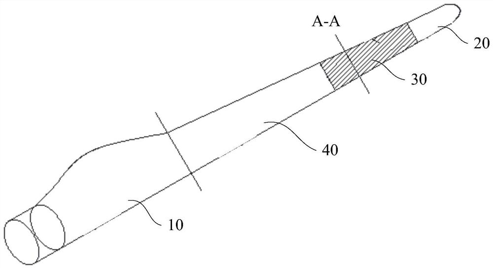
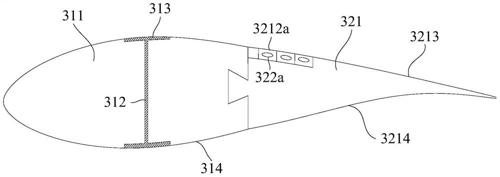
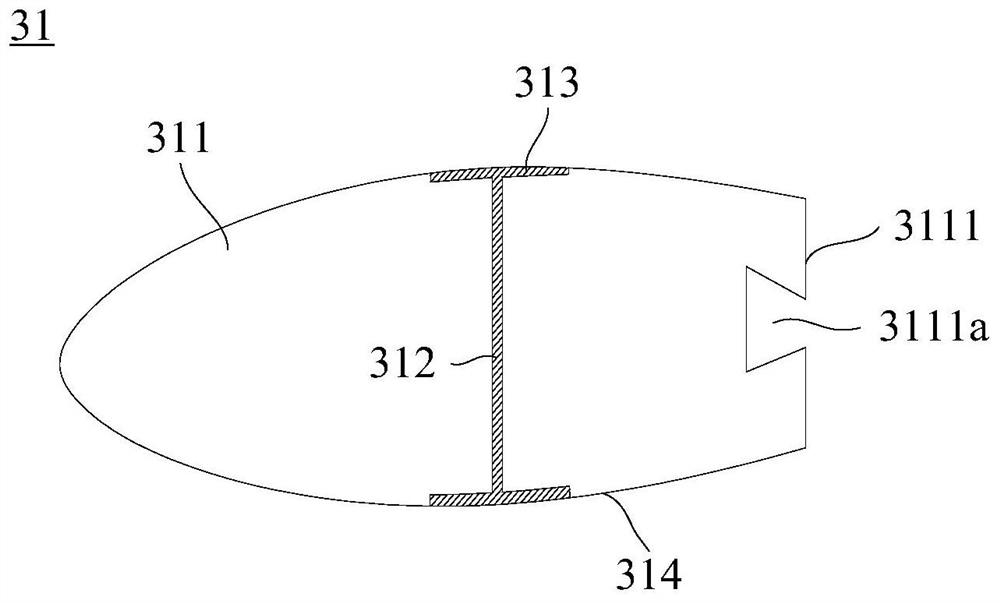
The invention provides an impeller, a blade and a blade section of a wind power generating set, the blade section includes a blade front section and a blade rear section, the blade front section includes a first main body, and the first main body includes a first connecting surface; the blade rear section includes a second main body and a blade rear section. The airbag, the second body is made of flexible material, the second body includes a second connection surface, the second body is fixedly connected with the first body; a cavity is arranged in the second body, the airbag is accommodated in the cavity, and the airbag includes an airbag wall , there is an air chamber in the airbag wall, when the environmental parameters at the location of the wind turbine meet the set parameter conditions, the volume of the gas in the air chamber increases, squeezing the airbag wall, causing the airbag wall to expand and squeeze the cavity The inner wall of the second main body expands at the corresponding position; when the environmental parameters meet the set parameter conditions, the blade stalls. The invention can effectively reduce the risk of blade stall.

Description

technical field [0001] The present invention relates to the field of wind turbines, in particular to an impeller, blades and blade segments of a wind turbine. Background technique [0002] The blades of wind turbines are the core components for absorbing wind energy, and the operating state of the blades directly affects the wind energy absorption efficiency, noise level and structural safety of wind turbines. Sometimes the wind turbines may run in the transitional section of the wind turbine due to the unreasonable blade design, the ambient air density during the operation of the wind turbine is significantly lower than the designed air density, and the expansion of the wind turbine. The operating range between the wind speed corresponding to the rotational speed and the wind speed corresponding to the rated power of the wind turbine) becomes longer, etc., so that there is a risk of local stall at the blade tip. The output power of the wind turbine after the stall is signi...

Claims


Application Information

Patent Timeline
Patent Type & Authority Patents(China)
IPC IPC(8): F03D1/06F03D7/04
CPCF03D1/0675F03D7/0256F03D7/022F05B2240/311F03D1/0658Y02E10/72
Inventor 徐浩然许移庆艾国远赵越罗红
Owner SHANGHAI ELECTRIC WIND POWER GRP CO LTD
Learn More