Centrifugal compressor having vane jet orifice

A centrifugal compressor and compressor technology, which is applied to the components of pumping devices for elastic fluids, mechanical equipment, machines/engines, etc., and can solve problems such as large flow loss, stall, surge, etc.

Inactive Publication Date: 2007-08-08
TSINGHUA UNIV
View PDF0 Cites 22 Cited by
  • Summary
  • Abstract
  • Description
  • Claims
  • Application Information

AI Technical Summary

Problems solved by technology

At the design flow rate, the impeller does work on the gas, and there is no large-scale flow separation phenomenon on the blade surface. thickening, large-scale flow separation phenomenon occurs, large-scale vortex generation, development and fragmentation, accompanied by large flow loss; when the flow rate is further reduced, the separation is more serious, which will lead to unstable operation of the compressor, resulting in stall or even surge

Method used


Image

  • Centrifugal compressor having vane jet orifice
  • Centrifugal compressor having vane jet orifice
  • Centrifugal compressor having vane jet orifice

Examples


Embodiment Construction

[0016] The specific embodiment of the present invention will be described with reference to the accompanying drawings.

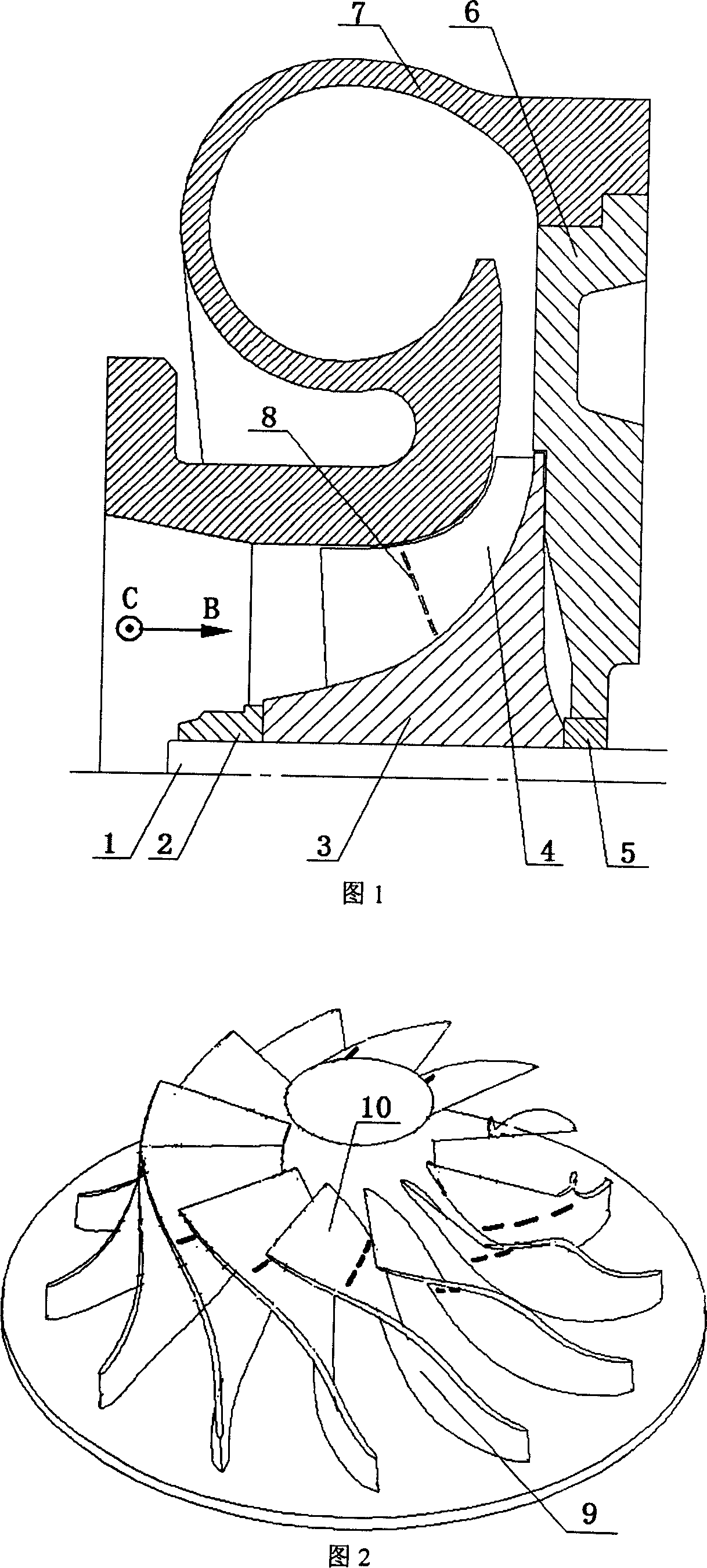
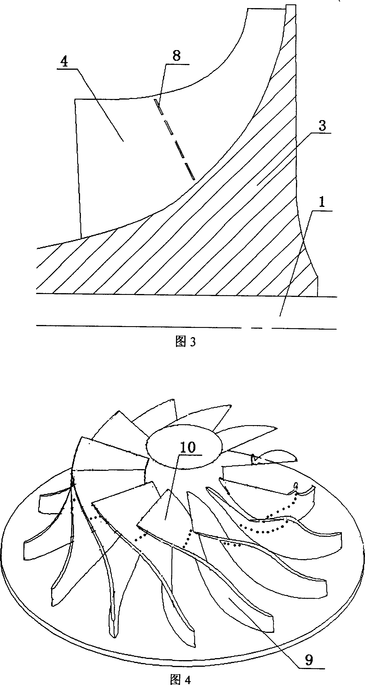
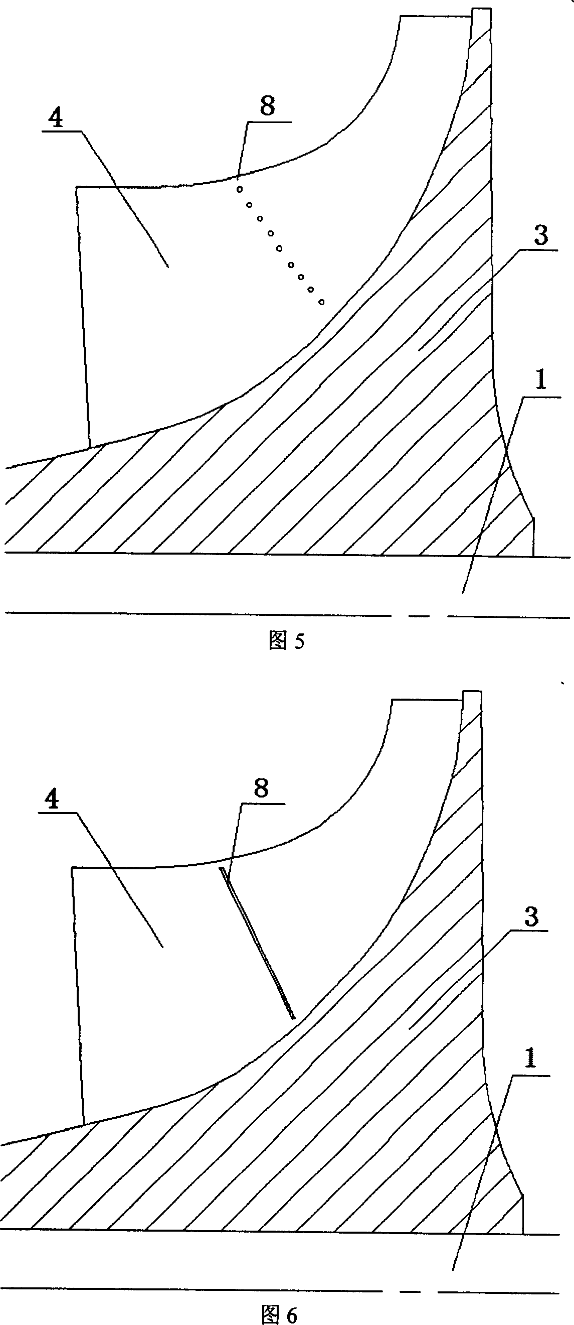
[0017] As shown in Fig. 1, the compressor rotating shaft 1, the impeller fixing bolt 2, the impeller 3, the blade 4, the seal block 5, the impeller back plate 6, and the volute 7 are common parts of the existing compressor. The present invention is characterized in that the blade 4 has the largest curvature along the mainstream direction, and a jet port 8 is opened along the blade height direction. During operation, under the action of the pressure difference between the two sides of the blade, a small stream of gas is sprayed from the pressure surface through the jet port 8 and from the suction surface. out. The jet port 8 can be one or more slits or a plurality of through holes, and Fig. 1 shows the situation of a plurality of slits. Where C represents the direction of rotation of the compressor impeller, and B represents the direction of inlet airflow. ...


PUM


Abstract

A centrifugal compressor with a jet orifice belonged to the turbo-machine field relates to the improvement of the booster centrifugal compressor used for vehicle and ships and aviation centrifugal compressor all the like turbo-machine box. It is characterized that a jet orifice set on the principal flow direction maximal curvature of the blade. Said jet orifice can be a narrow slit or two series-wound narrow slits along blade-high direction or a line of through-hole. The invention makes the suction surface of the impeller blade injected high energy jet flow when the centrifugal compressor operates via setting jet orifice on the blades, to activate the liquid in the boundary layer of the suction surface, thereby improving the ability for opposing adverse pressure gradient, to avoid impeller blade suction surface flow breakaway and improve the stalling allowance of the centrifugal compressor.

Description

Technical field: [0001] A centrifugal compressor with blade jet ports belongs to the technical field of impeller machinery, and relates to the improvement of impeller machinery casings such as centrifugal compressors for vehicle and marine turbochargers, industrial centrifugal compressors, and aviation centrifugal compressors. Background technique: [0002] Compared with the reciprocating compressor, impeller compressors such as centrifugal compressors have the advantages of high efficiency, light volume and weight, and stable operation, but their working conditions are limited. Under the low flow condition of the centrifugal compressor, there will be large-scale flow separation in the impeller and diffuser, resulting in unstable operation, stalling or even surge, which will directly lead to a sharp drop in compressor efficiency and pressure ratio, and a serious shortening of life. , or even directly damaged in a short period of time. [0003] The shapes of blades and diffu...

Claims


Application Information

Patent Timeline
Patent Type & Authority Applications(China)
IPC IPC(8): F04D29/30
Inventor 张扬军郭宫达郑新前徐建中诸葛伟林李亚卓
Owner TSINGHUA UNIV
Why Eureka
Try Eureka