Burner for combustion of a low-calorific fuel gas and method for operating a burner

A burner, low calorific value technology, applied in combustion methods, burners, combustion chambers, etc., can solve the problem of difficult to achieve good mixing of combustion air and syngas, avoid flashback, reduce pressure loss, improve The effect of spatial uniformity

Inactive Publication Date: 2007-09-19
SIEMENS AG
View PDF3 Cites 12 Cited by
  • Summary
  • Abstract
  • Description
  • Claims
  • Application Information

AI Technical Summary

Problems solved by technology

Good spatial mixing of combustion air and synthesis gas is difficult due to the high volume flow rate of synthesis gas required and the corresponding degree of spatial expansion in the mixing zone

Method used


Image

  • Burner for combustion of a low-calorific fuel gas and method for operating a burner
  • Burner for combustion of a low-calorific fuel gas and method for operating a burner
  • Burner for combustion of a low-calorific fuel gas and method for operating a burner

Examples


Embodiment Construction

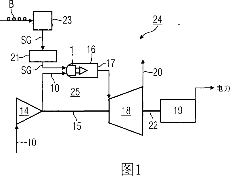
[0038] The power plant installation 24 shown in FIG. 1 comprises a gas turbine plant 25 and a gasification plant 23 for gasifying a fossil fuel B connected upstream of the gas turbine plant 25 . The gas turbine arrangement 25 includes a compressor 14 , a combustion chamber 16 and a turbine 18 connected downstream of the combustion chamber 16 . Compressor 14 and turbine 18 are coupled via a common rotor shaft 15 . A generator 19 connected downstream of the turbine 18 is coupled to said turbine via a generator shaft 22 . The combustion chamber 16 comprises a combustion space 17 and a burner 1 protruding into the combustion space 17 for burning a low calorific value gas SG obtained by gasifying a fossil fuel B in a gasification device 23 gas.

[0039] During operation of the gas turbine 18, air 10 is drawn into the compressor 14, where the air is highly compressed. The compressed air 10 is then fed to the burner 1 as combustion air 10 and mixed with the low calorific value gas...


PUM


Abstract

The invention relates to a burner (1), for the combustion of a low-calorific fuel gas (SG), with an air channel (2), running along a burner axis (12), for the introduction of combustion air (10) and a fuel gas channel (26), embodied for a high volumetric flow of low-calorific fuel gas (SG), whereby the fuel gas channel (26) and the air channel (2) open out into a mixing region (27). According to the invention, a low-nitrogen oxide synthesis gas operation of the burner (1) may be achieved, whereby a swirl element (4) is arranged in the air channel (2) for the generation of turbulent combustion air (10). The swirling element is provided in an opening region (28) directly adjacent to the flow of the mixing region (27). The invention further relates to a method of operation of a synthesis gas burner (1), whereby, directly before the mixing of the synthesis gas (SG) with the combustion air (10), the level of turbulence of the mass air flow is significantly increased on the microscopic level and a temporally and spatially homogenous mixing of the synthesis gas/air mixture is achieved.

Description

technical field [0001] The invention relates to a burner for burning gas with low calorific value, which has an air channel extending along the axis of the burner for conveying combustion air and a gas channel designed to allow the passage of low calorific gas with a large volume flow channels, wherein both the gas channel and the air channel lead to a mixing zone. [0002] Furthermore, the invention relates to a method of operating a burner in which a fossil fuel is gasified, the gasified fossil fuel being fed to said burner as low calorific value synthesis gas and mixed with combustion air to produce synthesis gas -Air mixture and combustion takes place in the combustion space. Background technique [0003] EP 0956475 B1 discloses a burner for burning high calorific value fuels such as natural gas or oil, which enables a largely homogeneous mixing of the high calorific value fuel and combustion air. For this purpose, a vortex generating element is installed inside the an...

Claims


Application Information

Patent Timeline
Patent Type & Authority Applications(China)
IPC IPC(8): F23R3/36F23R3/14
CPCF23R3/36F23D2900/14021F23D2900/14241F23R3/14F23R2900/00002
Inventor 安德烈亚斯·海洛斯伯索尔德·凯斯特林伯恩德·普拉德
Owner SIEMENS AG
Why Eureka
Try Eureka