Work flow model calibration method and device

A workflow and model technology, applied in the field of information processing, can solve problems such as unreachable activity 5, wrong workflow model, and failure to complete, to achieve simple conversion algorithms and path calculation algorithms, improve verification efficiency, and quickly calculate the amount Effect

Inactive Publication Date: 2008-04-30
KINGDEE SOFTWARE(CHINA) CO LTD
View PDF0 Cites 3 Cited by
  • Summary
  • Abstract
  • Description
  • Claims
  • Application Information

AI Technical Summary

Problems solved by technology

[0007] For example, referring to the schematic diagram shown in Figure 1a, if And and Xor are not paired, it is known that there may be errors in the workflow model. From specific analysis, it can be known that for the workflow model shown in Figure 1, there may be multiple instances of activity 5, However, activities 2, 3, and 4 may not be completed
[0008] For another example, referring to the schematic diagram shown in Figure 1b, and And and Xor are not paired, it is known that there may be errors in the workflow model, and specific analysis shows that for the workflow model shown in Figure 1b, activity 5 cannot reach
[0009] However, the above-mentioned verification of the workflow model directly through the pairing of And and Xor can only handle simple scenarios, and it cannot be calculated correctly for complex graph forms.
As shown in Figure 2, the number of connecting arcs of And is more than that of Xor, but after analyzing the workflow model in detail, it is found that there is no error in it, that is, the existing verification method may cause errors

Method used


Image

  • Work flow model calibration method and device
  • Work flow model calibration method and device
  • Work flow model calibration method and device

Examples


example 1

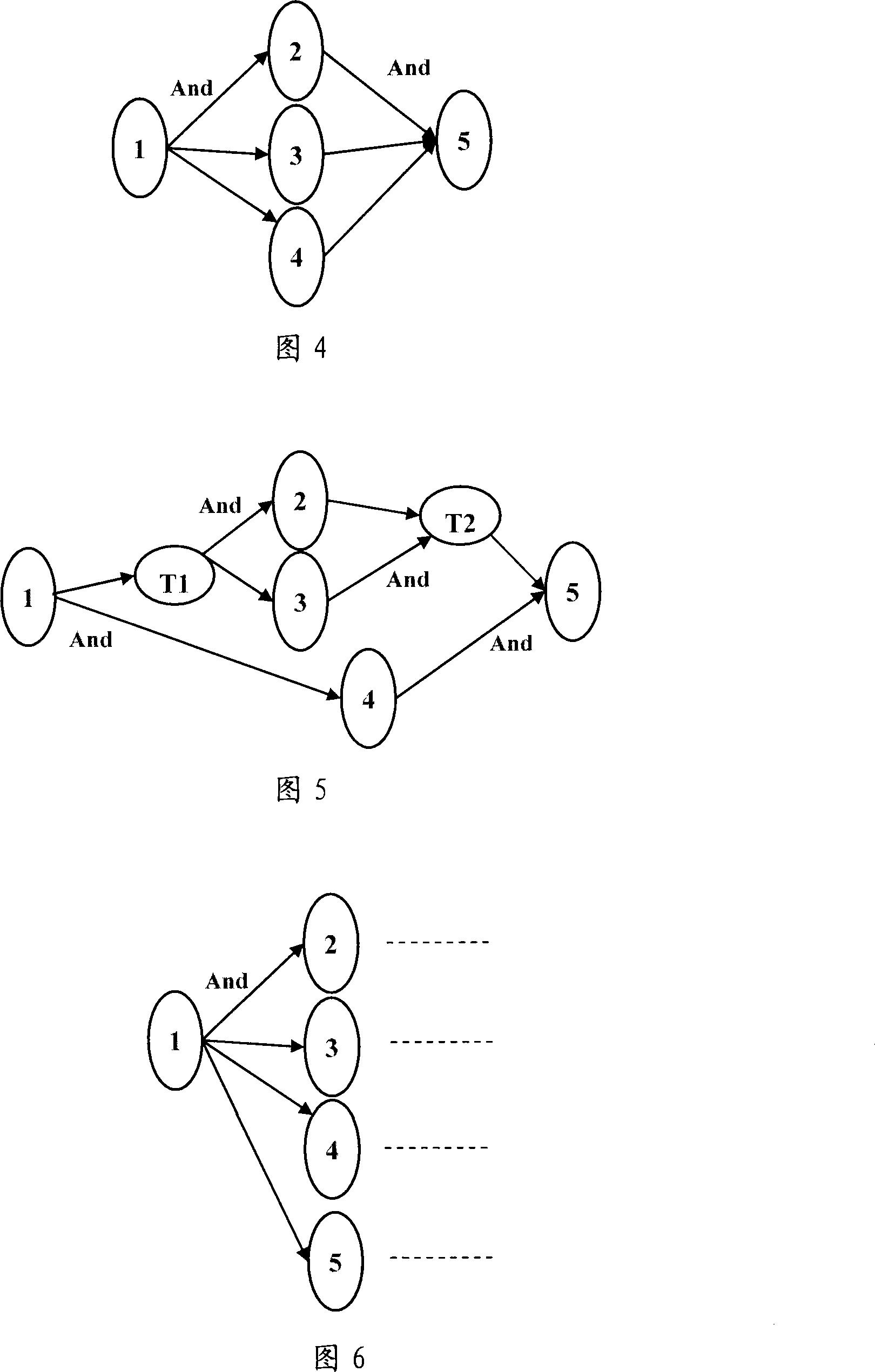
[0068] Referring to Figure 4, the entry and exit modes of the original process model are AndSplit and AndJoin respectively. Referring to Figure 5, after converting to an ideal model, two new temporary nodes T1 and T2 are added, and the entry and exit modes are also Andsplit and Andjoin. In this way, when all paths are calculated at the end, the sum of Andsplit is the same as the sum of AndJoin, indicating that they are completely matched.

example 2

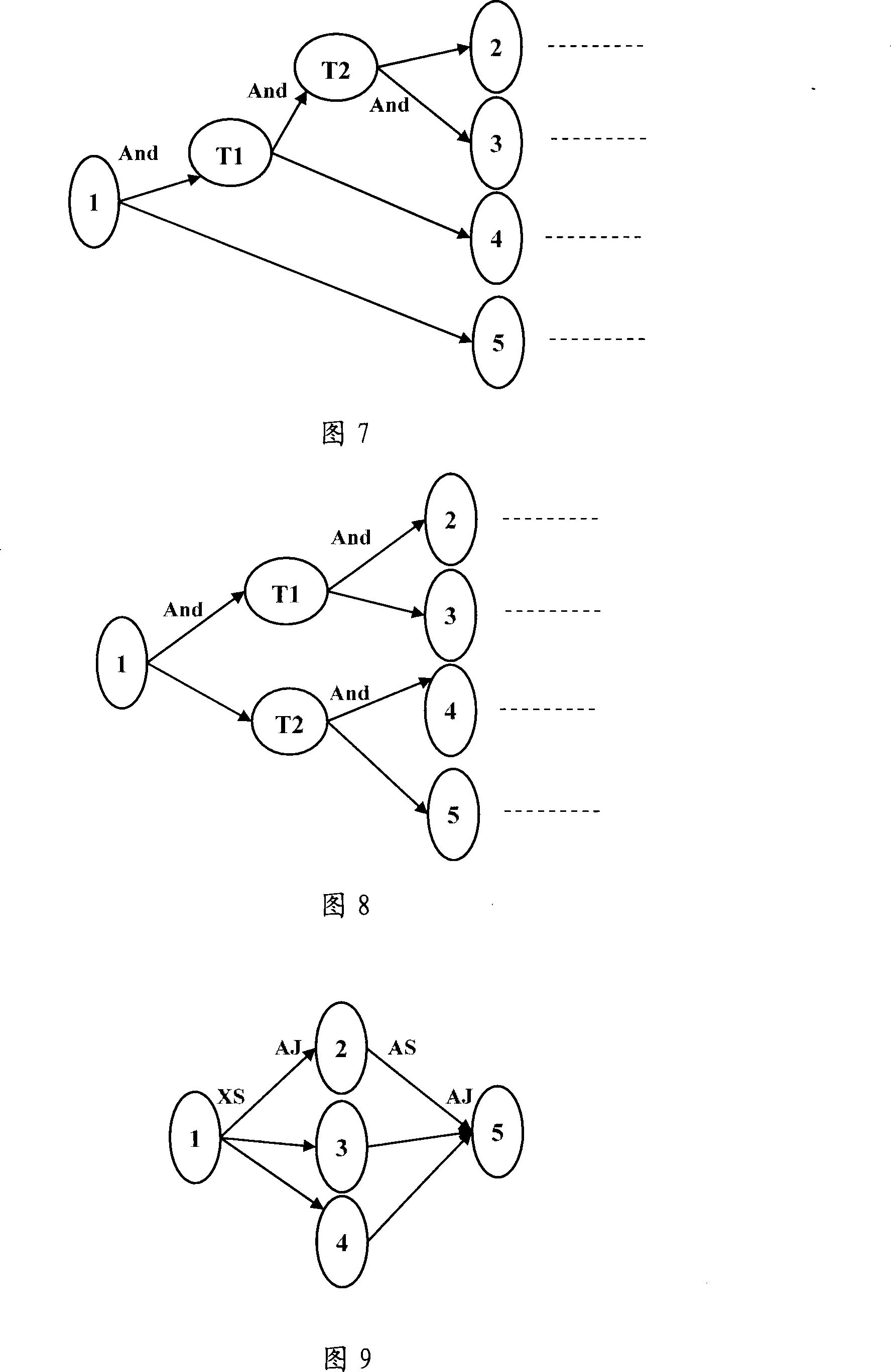
[0070] Referring to Figure 9, the export mode of node 1 is XorSplit, and the import and export modes of other nodes are both AndSplit and AndJoin. Of course, in the schematic diagram of Figure 9, although the entry and exit modes of node 2 are both AndSplit and AndJoin, only one entry connection arc and one exit connection arc are shown in Figure 9, which is for the sake of convenience and does not show Full picture of a complete, complex workflow model.

[0071] Referring to Figure 10, after converting to an ideal model, two new virtual empty nodes T1 and T2 are added, T1 inherits the entry and exit modes of node 1 as XorJoin and XorSplit, and T2 inherits the entry and exit modes of node 2 as AndJoin and AndSplit.

[0072] Then traverse all paths from node 1 to node 5 by the present invention, when calculating the path {node 1-node T1-node 2-node T2-node 5}, the obtained entry and exit mode set is (XS, XJ, XS, AJ, AS, AJ, AS), so through simple calculation, it can be clearly...


PUM


Abstract

The invention provides a solving proposal for a correcting a working stream model, and may particularly includes converting a to-be-corrected working stream model into an ideal model each node of which has at most two outlet connecting arcs and at most two inlet connecting arcs; traversing all paths from a starting node to a stopping node in the ideal model to obtain outlets / inlets mode set of all nodes in the paths; judging whether outlet / inlet mode of each path is matched; and defining the model is qualified if outlet / inlet mode is each path is matched, and otherwise, defining the working stream model has defect. The solving proposal provided in the invention can be automatically carried out by a computer without requirement for manual intervention. By increasing the step for converting into ideal model, arithmetic for calculation is simplified and accuracy of correction is improved. Further, the invention is simple (the conversion arithmetic and path calculation arithmetic are simple) and rapid (arithmetic load is small) and has improved correction efficiency.

Description

technical field [0001] The invention relates to the technical field of information processing, in particular to a verification method and device for a workflow model. Background technique [0002] Organizations such as enterprises and government agencies are a complex system. View these organizations from a process perspective. The constituent elements of an organization are processes, and the constituent elements of a process are activities; the workflow model is an abstract representation of these business processes. Used to describe the individual elements of a workflow and their relationships. [0003] A complete business process of an organization is composed of a series of the most basic production activities according to a certain logical sequence and rules. These production activities and the logical relationship between them can be intuitively mapped into a network consisting of nodes and connecting arcs directed graph. A node in a directed graph represents an exe...

Claims


Application Information

Patent Timeline
IPC IPC(8): G06Q10/00G06Q10/06
Inventor 宋凯
Owner KINGDEE SOFTWARE(CHINA) CO LTD
Why Eureka
Try Eureka