

Pressure breaking device
A technology of high-pressure drive and low-pressure drive, which is applied to valve devices, safety valves, engine components, etc., can solve problems such as low reliability, complex structure, troublesome manufacturing, etc., and achieve improved practicability and reliability, strong reliability, and low cost cheap effect
- Summary
- Abstract
- Description
- Claims
- Application Information
AI Technical Summary
Problems solved by technology
Method used
Image

Examples
Embodiment Construction
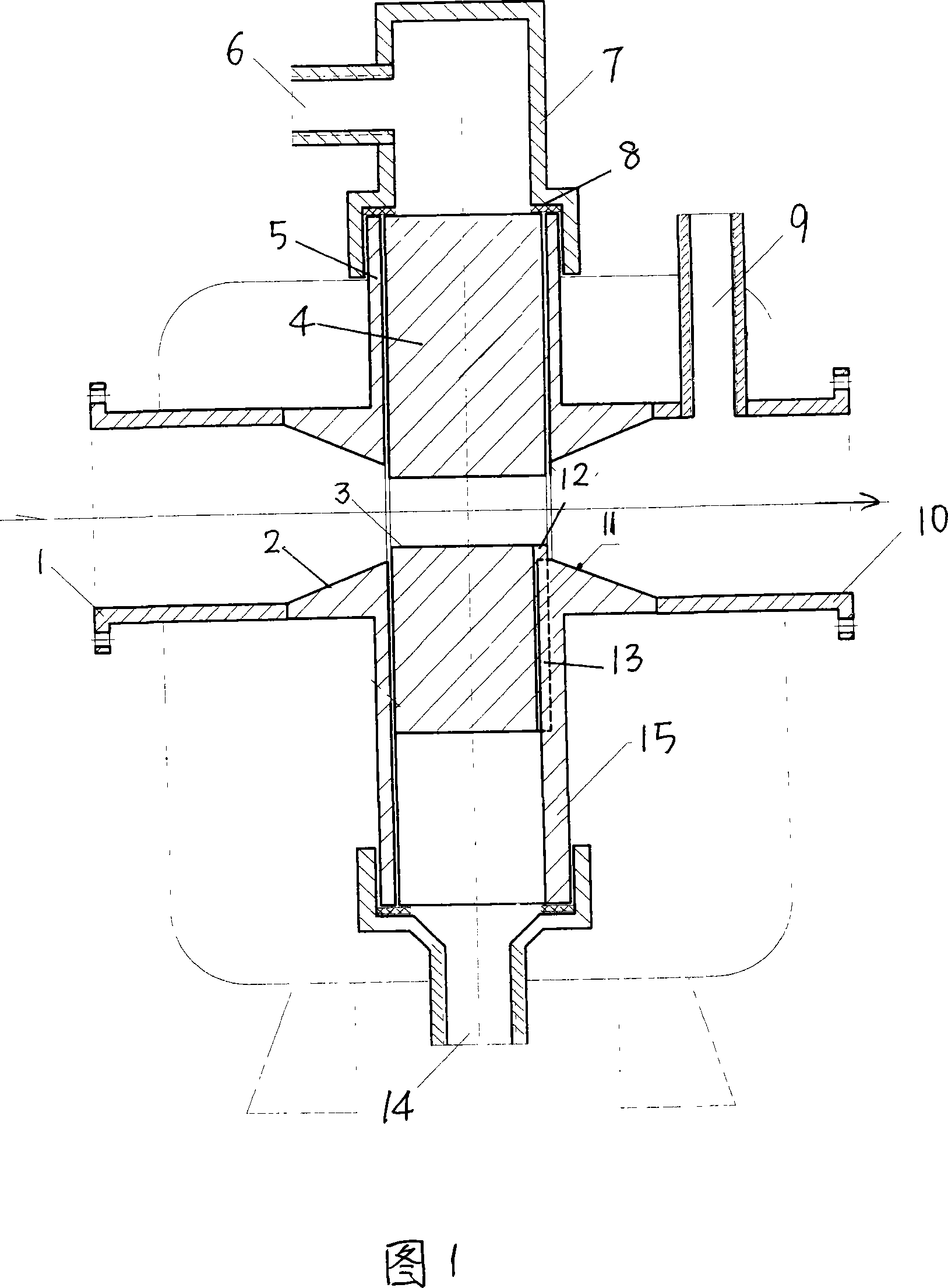
[0014] Referring to Fig. 1, it is a cross-shaped four-way round pipe. The two horizontal pipes are the water inlet pipe 1 and the water outlet pipe 10 respectively. Air outlet pipe and mouth 9; The upper and lower two pipes in the vertical direction are respectively low-pressure drive pipe 5 and high-pressure drive pipe 15, and the position-limiting part in the said high-pressure drive pipe is to connect funnel-shaped 14 water inlet pipes at its lower end, The limiting part in the said low-pressure driving tube is that the convex end cap 7 is terminated on it, and the inner cavity wall forms a limiting boss 8, and the low-voltage driving nozzle 6 is opened on the side of the convex end cap. There is an adjusting cylinder 4 in the inner cavity of the low-pressure drive tube, and a horizontal through hole 3 is arranged on the cylinder body. The position of the horizontal through hole is that when the adjusting cylinder goes up to the limit boss 8, the horizontal through hole conn...
PUM
 Abstract
Description
Claims
Application Information